Internal Devices
Tiger City IMX Industrial Computer with Linux OS
- Internal expansion connector
- Watchdog + reset
- EEPROM
- FLASH
- RTC
- ESP32 microcontroller
- TPM 2.0
- Secure element TO136
- Buzzer
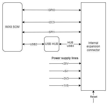
Internal expansion connector
Part number: FH1234-221CWG0MUT01
Internal expansion connector connections diagram
Internal expansion connector connections table
|
Connector pin |
Description |
|
1 |
GND |
|
2 |
VIN |
|
3 |
GND |
|
4 |
SPI1 MOSI |
|
5 |
GND |
|
6 |
SPI1 SCLK |
|
7 |
GND |
|
8 |
SPI1 MISO |
|
9 |
GND |
|
10 |
RTC battery power supply |
|
11 |
External watchdog reset |
|
12 |
NC |
|
13 |
GND |
|
14 |
NC |
|
15 |
NC |
|
16 |
NC |
|
17 |
GPIO4 IO25 |
|
18 |
GND |
|
19 |
GPIO1 IO07 |
|
20 |
GPIO4 IO21 |
|
21 |
GPIO5 IO09 |
|
22 |
Global reset |
|
23 |
GND |
|
24 |
I2C3 SDA |
|
25 |
I2C3 SCL |
|
26 |
GND |
|
27 |
+3V3 |
|
28 |
GND |
|
29 |
USB3 positive pole |
|
30 |
USB3 negative pole |
|
31 |
GND |
|
32 |
+20V |
|
33 |
UIO reset |
|
34 |
NC |
|
35 |
NC |
|
36 |
+1V8 |
|
37 |
+1V8 |
|
38 |
GND |
|
39 |
+5V |
|
40 |
+5V |
|
41 |
GND |
|
42 |
GND |
|
43 |
VIN |
|
44 |
GND |
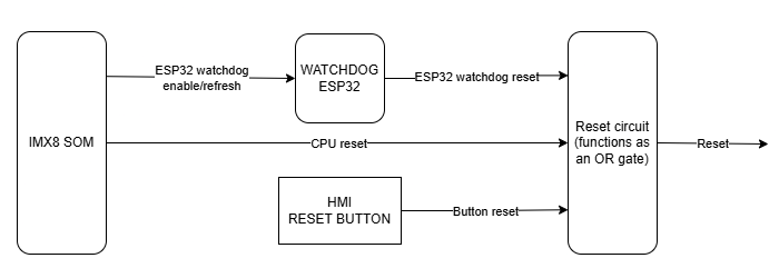
Watchdog + reset
The device is equipped with a watchdog and a reset circuit.
Watchdog and reset circuit connections diagram
CPU connections table
|
Signal |
Default function |
User-space name |
|
|
ESP32_WDI |
GPIO1_IO01 |
gpiochip0 1 |
ESP32_WDI |
|
SOM_GLOB_NRST |
GPIO5_IO02 |
gpiochip4 2 |
GLOBAL_NRST |
|
GPIO0 |
GPIO3_IO22 |
gpiochip2 22 |
ESP_GPIO0 |
|
GPIO2 |
GPIO3_IO20 |
gpiochip2 20 |
ESP_GPIO2 |
|
ESP_CHIP_PU |
GPIO4_IO20 |
gpiochip3 20 |
ESP_CHIP_PU |
ESP32 reset
The device is equipped with an ESP32 microcontroller as a watchdog.
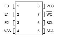
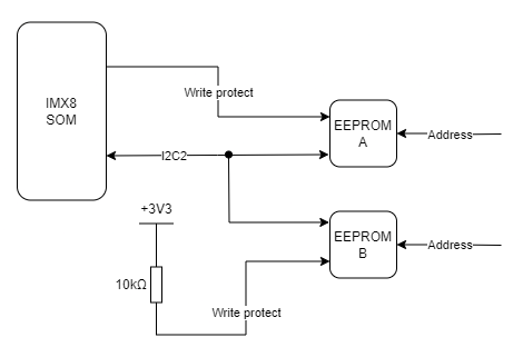
EEPROM
The device is equipped with 2 EEPROM memory modules. EEPROM B is read-only and reserved for the producer's purposes.
EEPROM device
Part number: M24C02-RMC6
EEPROM A connections table
|
EEPROM pin |
Description |
User-space name |
|
1 |
Address pin 0 (GND) |
X |
|
2 |
Address pin 1 (+3V3) |
X |
|
3 |
Address pin 2 (+3V3) |
X |
|
5 |
I2C2 data |
X |
|
6 |
I2C2 clock |
X |
|
7 |
EEPROM write-protect |
gpiochip0 2 |
EEPROM B (EEPROM SN) connections table
|
EEPROM pin |
Description |
User-space name |
|
1 |
Address pin 0 (GND) |
X |
|
2 |
Address pin 1 (+3V3) |
X |
|
3 |
Address pin 2 (GND) |
X |
|
5 |
I2C2 data |
X |
|
6 |
I2C2 clock |
X |
|
7 |
EEPROM write-protect (pull-up) |
X |
EEPROM connection diagram
User-space access
EEPROM device name: /sys/bus/nvmem/devices/1-00561
EEPROM device address: 0x56
I2C2
EEPROMs A and B are connected to the CPU with the I2C2 interface.
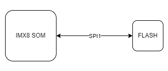
FLASH
Part number: W25Q64JVSSIQ
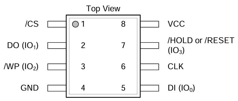
FLASH connections table
|
FLASH pin |
Description |
User-space name |
|
1 |
SPI1_CS0 |
gpiochip2 21 |
|
2 |
SPI1_MISO |
X |
|
3 |
SPI1_WP |
X |
|
5 |
SPI1_MOSI |
X |
|
6 |
SPI1_SCLK |
X |
|
7 |
SPI1_HOLD |
X |
FLASH connection diagram
User-space access
FLASH device name: /dev/mtdblock0
SPI1
FLASH is connected to the CPU with the SPI1 interface.
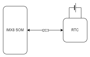
RTC
The device is equipped with a real-time clock operating at 32.768 kHz with a tolerance of 20 ppm. The RTC clock is connected to a DR2032 battery which serves as its power supply.
RTC device
Part number: DS1338
RTC connection diagram
User-space access
Device name: /sys/class/rtc/rtc0
Device address: 0x68
RTC connections table
|
RTC pin |
Description |
|
1 |
Clock oscillator pin no. 1 |
|
2 |
Clock oscillator pin no. 2 |
|
3 |
Battery power pin |
|
5 |
I2C3 data |
|
6 |
I2C3 clock |
I2C3
The real-time clock is connected to the CPU with the I2C3 interface.
ESP32 microcontroller
The device is equipped with an internal ESP32 microcontroller that can be used for internal purposes.
ESP32 device
Part number: ESP32-DOWD
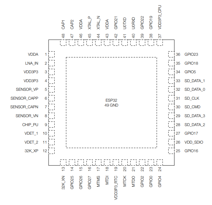
ESP32 connections table
|
ESP32 pin |
Description |
|
8 |
ESP_P_DETECT |
|
9 |
ESP_CHIP_PU |
|
14 |
ESP32_WDT_EN |
|
15 |
ESP32_WDI |
|
22 |
ESP_GPIO2 |
|
23 |
ESP_GPIO0 |
|
24 |
RESET_WDT |
|
25 |
LED_ESP |
|
26 |
VDD_SDIO |
|
28 |
ESP_SPI_HD |
|
29 |
ESP_SPI_WP |
|
30 |
ESP_SPI_CS0 |
|
31 |
ESP_SPI_CLK |
|
32 |
ESP_SPI_Q |
|
33 |
ESP_SPI_D |
|
38 |
I2C4_SCL |
|
39 |
I2C4_SDA |
|
40 |
ESP_CONSOLE_RX |
|
41 |
ESP_CONSOLE_TX |
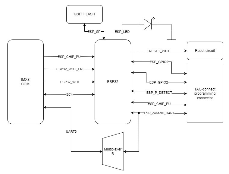
ESP32 connections diagram
CPU connections table
|
Signal |
CPU pin |
Default function |
User-space name |
|
ESP_GPIO_0 |
AC14 | GPIO3_IO22 | gpiochip2 22 |
| ESP_GPIO_2 | AC15 | GPIO3_IO20 | gpiochip2 20 |
|
ESP32_WDI |
AF14 | GPIO1_IO01 | gpiochip0 1 |
|
ESP32_WDT_EN |
AF13 |
GPIO1_IO03 |
gpiochip0 3 |
I2C4
The microcontroller is connected to the CPU via the I2C4 interface.
UART3
The microcontroller is connected to the CPU via the UART3 interface.
TPM 2.0
The device is equipped with a trusted platform module in 2.0 standard.
TPM device
Part number: SLM9670
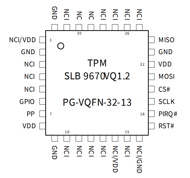
TPM connections table
|
TPM pin |
Description |
|
17 |
Reset |
|
18 |
TPM_IRQ |
|
19 |
SPI2 clock |
|
20 |
SPI2 chip select 0 |
|
21 |
SPI2 master out slave in |
|
24 |
SPI2 master in slave out |
User-space access
Device name: /sys/class/tpm
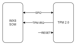
TPM connection diagram
CPU connections table
|
Signal |
CPU pin |
Default function |
User-space name |
|
TPM_IRQ |
AC24 |
GPIO4_IO23 |
gpiochip3 23 |
|
SPI2_CS0_TPM |
A6 |
GPIO5_IO13 |
gpiochip4 13 |
SPI2
The trusted platform module is connected to the CPU with the SPI2 interface.
Secure element TO136
The device is equipped with a secure element that can be used for data encoding.
Secure element device
Part number: IDEMIA TO136
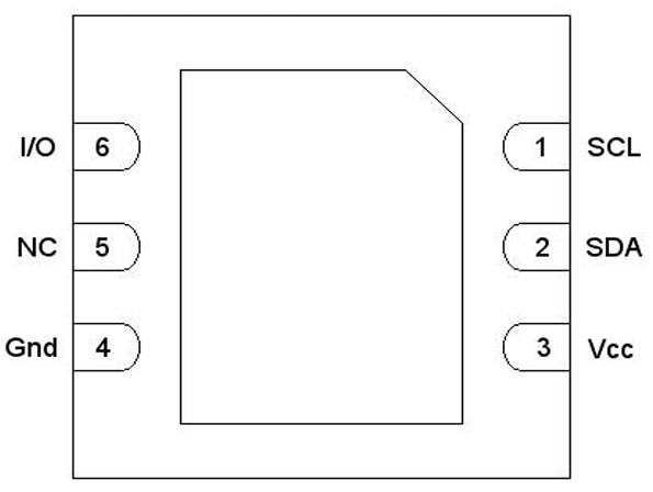
Secure element connections table
|
Secure element pin |
Description |
|
1 |
I2C4 clock |
|
2 |
I2C4 data |
|
3 |
+3V3 |
|
6 |
IDLE/BUSY state report |
User-space access
Device address: 0x50
Secure element connections diagram
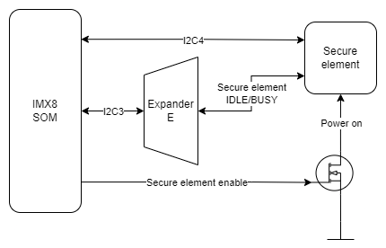
Expander E
The secure element is connected to the Expander E connected to the CPU via the I2C3 interface.
I2C4
The secure element is connected to the CPU via the I2C4 interface.
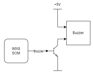
Buzzer
The device is equipped with a buzzer.
Buzzer device
Part number: LD-BZEG-0905
User-space access
Device name: gpiochip3 7
Label: "BUZZER"
Buzzer connection diagram