Front Panel
{{@273#bkmrk-tiger-city-imx-embed}}
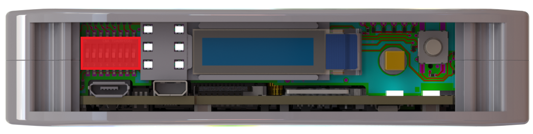
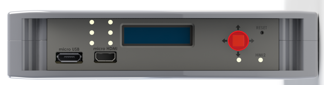
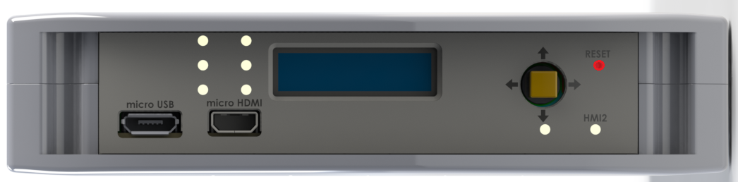
View of the front panel
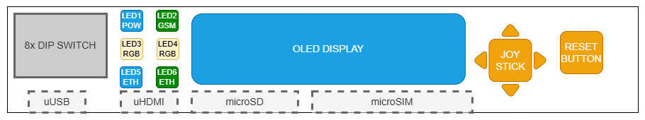
Components of the front panel
- {{@135#bkmrk-dip-switch}}
- {{@135#bkmrk-signal-leds}}
- {{@135#bkmrk-oled-display}}
- {{@135#bkmrk-%C2%A0}}
- {{@135#bkmrk-reset-button}}
DIP switches
The device has DIP switches on the front panel which enable the control of various key functions such as:
- booting mode choice
- microUSB signal choice
- choosing Linux console or RS232 signal
- user-written code
DIP switches placement on the front panel
Switch options
|
Switch No. |
Positions |
Description |
|
1 |
OFF - eMMC boot ON - USB boot |
Boot select - switching between booting device |
|
2 |
OFF - SOM USB ON - UART4 (Linux console) |
USB select - microUSB signal choice |
|
3 |
OFF - UART1<=>RS232_1 ON - UART4<=>RS232_1 |
RS232 - SOM UART RS232 select |
|
4 |
OFF - UART3<=>RS232_2 ON - UART3<=>ESP32 |
RS232 - SOM UART RS232/ESP32 select |
|
5 |
Unassigned |
Currently not used |
|
6-8 |
OFF/ON |
User options |
Connections diagram
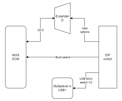
{{@136#bkmrk-expander-d}}
User-defined DIP switch options are connected to the expander D which is connected to the CPU via the I2C3 interface.
{{@133#bkmrk-usb1}}
The USB MUX select 1 and the USB MUX select 2 signals are connected to the multiplexer A associated with USB1.
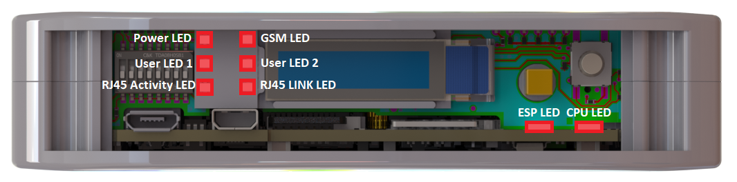
Signal LEDs
The device is equipped with 8 LEDs. 2 of these LEDs are placed on the mainboard, while the other 6 are on the front panel of the HMI board.
LEDs location
LEDs connections
|
Description |
User-space name |
Flags |
| Power LED |
gpiochip6 9 |
"LED_5V" |
| CPU LED |
|
"LED_MAINBOARD" |
|
User LED 1 G |
|
"LED3_GREEN" |
|
User LED 1 R |
|
"LED3_RED" |
|
User LED 1 B |
|
"LED3_BLUE" |
|
User LED 2 G |
|
"LED4_GREEN" |
|
User LED 2 R |
|
"LED4_RED" |
|
User LED 2 B |
|
"LED4_BLUE" |
LEDs connection diagram
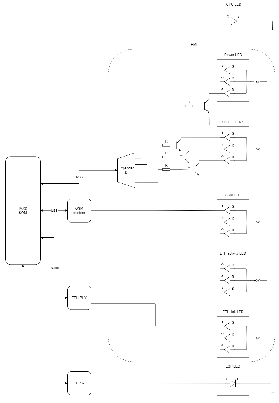
{{@166#bkmrk-esp32-microcontrolle}}
ESP LED is connected directly to the ESP32 microcontroller.
{{@133#bkmrk-%C2%A0-4}}
GSM LED is connected directly to the GSM modem.
{{@133#bkmrk-%C2%A0-3}}
ETH activity LED and ETH link LED are connected directly to the ETHERNET physical layer.
{{@136#bkmrk-expander-d}}
Power LED, User LED 1 and User LED2 are connected to the expander D which is connected to the CPU via the I2C3 interface.
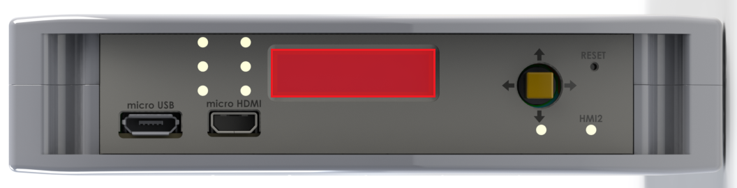
OLED display
The device is equipped with a 0.87” black and white display with a resolution of 128x32 px.
OLED display placement
OLED device
Part number: SCE087002-V01
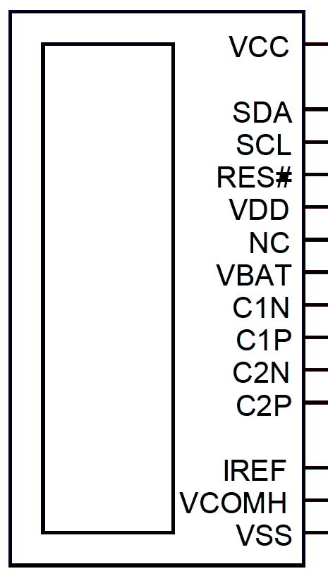
OLED connections table
|
OLED pin |
Description |
User-space name |
|
RES# |
RESET |
X |
|
SCL |
I2C3 clock |
X |
|
SDA |
I2C3 data |
X |
|
VCC |
OLED ON/OFF |
|
OLED connections diagram
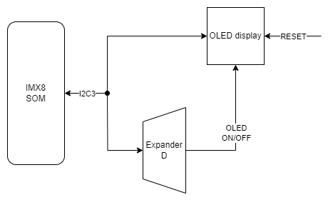
{{@136#bkmrk-expander-d}}
The OLED display is connected to Expander D which is connected to the CPU via the I2C3 interface.
{{@134#bkmrk-i2c4}}
The OLED display is directly connected to the CPU via the I2C3 interface.
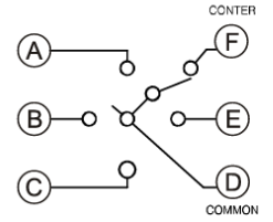
Joystick
The device is equipped with a joystick for controlling its functions.
Placement
Device
Part number: INT-1500D
Connections table
|
Joystick signal |
Expander D pin |
User-space name |
Flags |
|
Right |
20 |
|
"JOY_RIGHT" |
|
Up |
18 |
|
"JOY_UP" |
|
Left |
17 |
|
"JOY_LEFT" |
|
Down |
19 |
|
"JOY_DOWN" |
|
Push |
21 |
|
"JOY_PUSH" |
Connection diagram
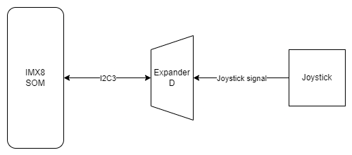
{{@136#bkmrk-expander-d}}
Joystick is connected to the Expander D which is connected to the CPU via the I2C3 interface.
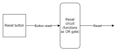
Reset button
The device has a reset button on the front panel.
Reset button location
Connections diagram