Front Panel
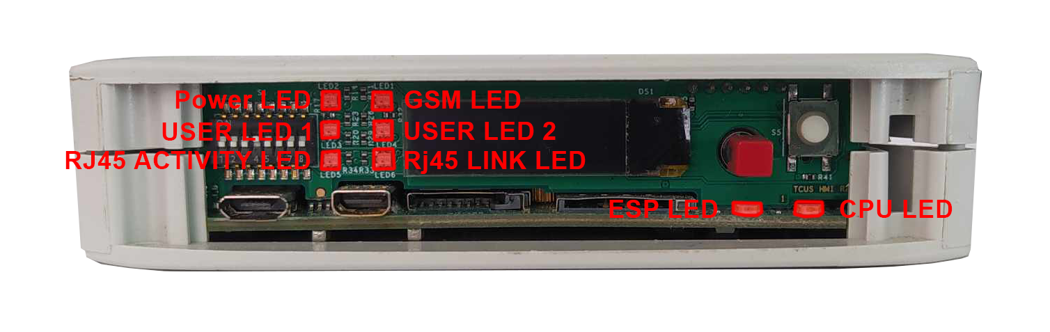
View of the front panel
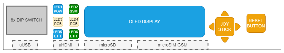
Components of the front panel
DIP switch
The device has a DIP switches on the front panel which enable the control of various key functions such as:
- booting mode choice
- microUSB signal choice
- choosing Linux console or RS232 signal
- realisation of a user written code
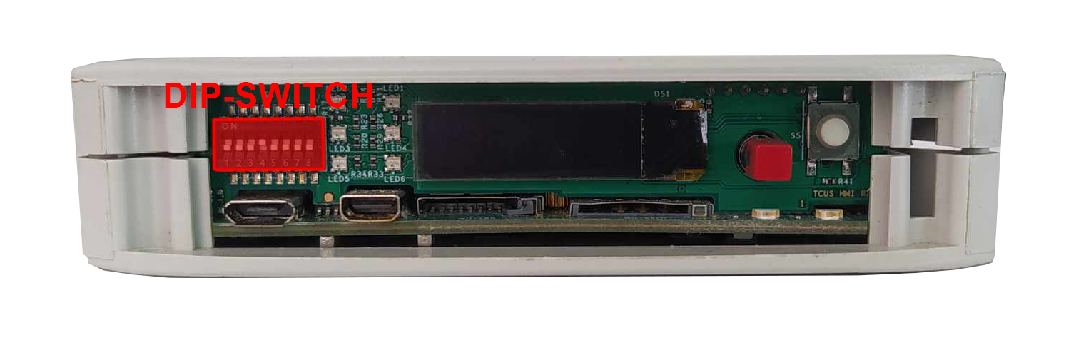
DIP switch placement on front panel
Switch options
|
Switch No. |
Positions |
Descripton |
|---|---|---|
|
1 |
OFF- eMMC boot ON - USB boot |
Boot select - switching between booting device |
|
2 |
2: OFF 3: OFF - SOM USB 2: ON 3: OFF - none 2: OFF 3: ON - UART4 (Linux console) 2: ON 3: ON - ESP UART |
USB select - microUSB signal choice |
|
3 |
||
|
4-5 |
Unassigned |
Currently not used |
|
6-8 |
OFF/ON |
User options |
Connections diagram
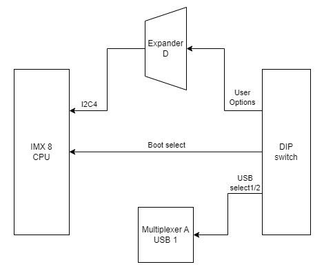
Expander D
User defined DIP-Switch options are connected to the expander D which is connected to the CPU via I2C4 interface.
USB1
USB select 1 and USB select 2 signals are connected to the multiplexer A associated with USB1.
Signal LEDs
The device is equipped with total of 8 LEDs. 2 of these LEDs are placed on the mainboard, while the other 6 are on the front panel of the HMI board.
LEDs location
LEDs connections
|
Description |
User space name |
|---|---|
|
CPU Led |
gpiochip8 8 |
|
User Led 1 G |
gpiochip7 10 |
|
User Led 1 R |
gpiochip7 5 |
|
User Led 1 B |
gpiochip7 12 |
|
User Led 2 G |
gpiochip7 13 |
|
User Led 2 R |
gpiochip7 11 |
|
User Led 2 B |
gpiochip7 15 |
LEDs connection diagram
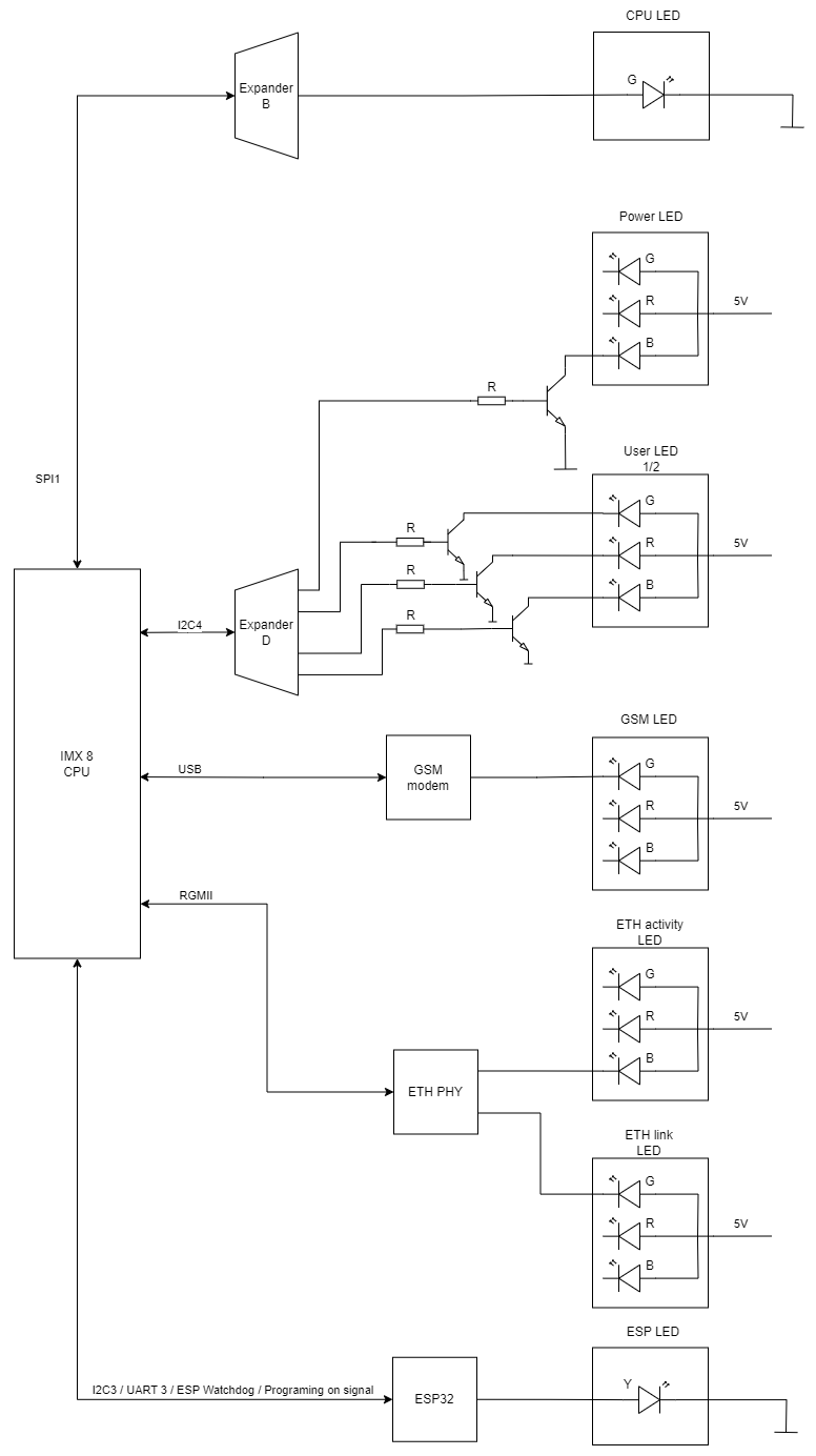
ESP32 microcontroller
ESP LED is connected directly to the GSM modem.
GSM
GSM LED is connected directly to the GSM modem.
ETHERNET
ETH activity LED and ETH link LED are connected directly to the ETHERNET physical layer.
Expander B
CPU LED is connected to the expander B which is connected with CPU via SPI1 interface.
Expander D
Power LED, User LED 1 and User LED2 are connected to the expander D which is connected with CPU via I2C4 interface.
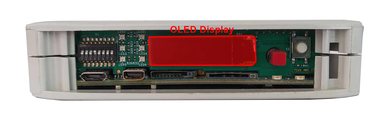
OLED display
The device is equipped with a 0.87” black and white display with resolution of 128x32 px.
OLED display placement
OLED device
Part number: SCE087002-V01
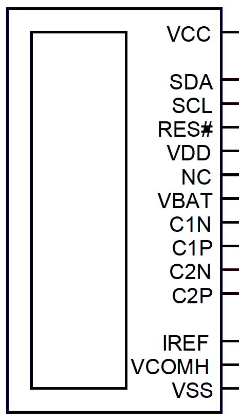
OLED connections table
|
OLED pin |
Description |
User space name |
|---|---|---|
|
RES# |
RESET |
X |
|
SCL |
I2C4 clock |
X |
|
SDA |
I2C4 data |
X |
|
VCC |
OLED ON/OFF |
gpiochip7 14 |
OLED connections diagram
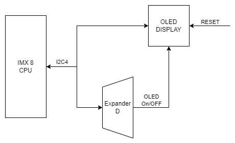
Expander D
The OLED display is connected to the Expander D which is connected to the CPU via I2C4 interface.
I2C3
The OLED display is directly connected to the CPU via I2C4 interface.
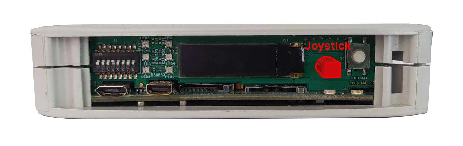
Joystick
The device is equipped with a joystick used for controlling its functions.
Placement
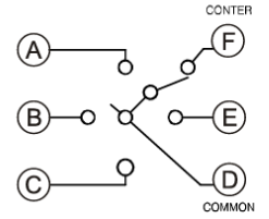
Device
Part number: INT-1500D
Connections table
|
Joystick signal |
Expander D pin |
User space name |
|---|---|---|
|
Right |
20 |
gpiochip7 3 |
|
Up |
18 |
gpiochip7 1 |
|
Left |
17 |
gpiochip7 0 |
|
Down |
19 |
gpiochip7 2 |
|
Push |
21 |
gpiochip7 4 |
Connection diagram
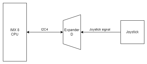
Expander D
Joystick is connected to the Expander D which is connected to the CPU via I2C4 interface.
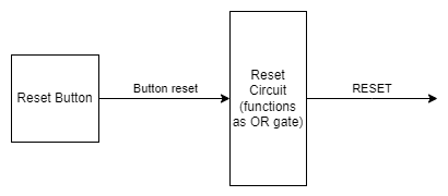
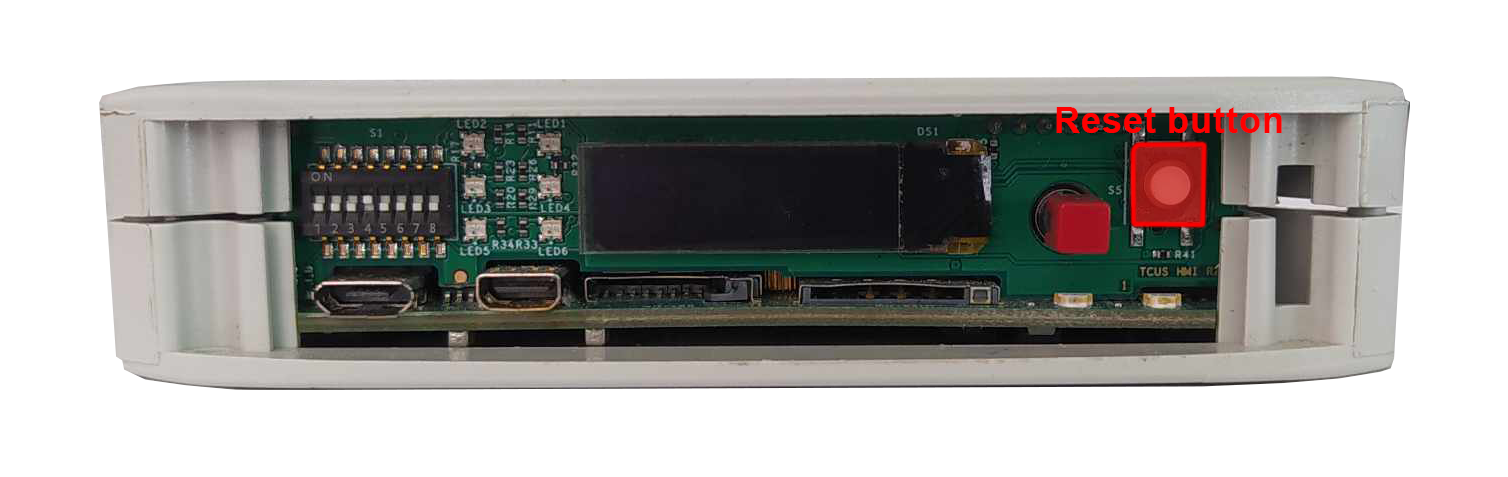
Reset button
The device has a reset button on the front panel.
Reset button location
Connections diagram