Tiger City IMX
Tiger City IMX Industrial Computer with Linux OS documentation
- Data Sheet
- Get Started
- Hardware
- Introduction
- Technical Diagrams
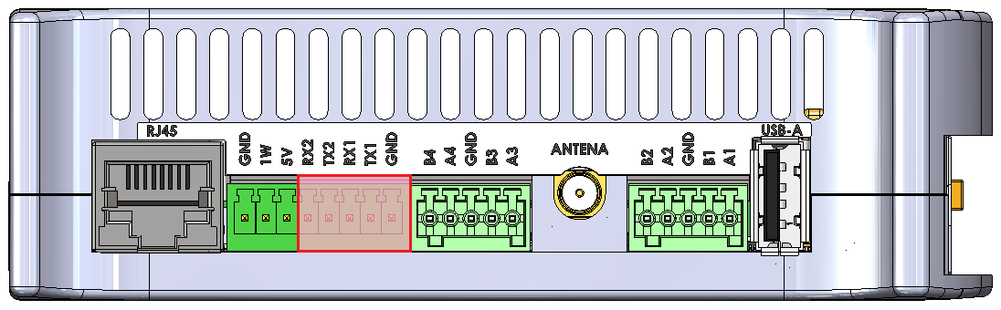
- External Interfaces
- Internal Devices
- Front Panel
- Expanders
- Connectors Designations
- Linux OS
- Booting
- System Console
- User Management
- Updating
- System Overview
- Restoring Factory Settings
- Building Custom System Image
- Software Examples
- Contact Us
- Common Resources
Data Sheet
Tiger City IMX Industrial Computer with Linux OS
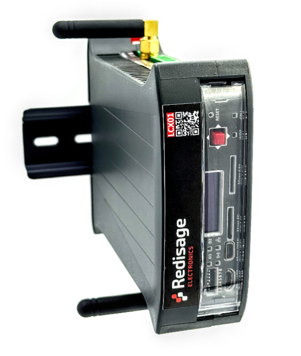
The Tiger City IMX minicomputer uses Linux operating systems and is equipped with several communication interfaces such as: Ethernet, USB 2.0, HDMI, GSM, RS232, RS485, 1-Wire and multiple analog-digital inputs and outputs. It can also be configured to include a Wi-Fi module and encryption modules that increase the security of the device. The casing enables installation on the DIN rail. The front panel has switches, an OLED display and a joystick for manual control of the device operation.
|
TCX IMX8
|
Features:
|
Specifications
|
Redisage PN |
LCX01 |
LCX02 |
LCX03 |
LCX04 |
LCX05 |
LCX06 |
|
|
Version |
Light |
Light GSM |
Basic |
Basic GSM |
Max |
Max GSM |
|
|
Power input |
12-24 VDC +-20%, maximum power 25 W, reverse polarity protection | ||||||
|
System on Module |
VAR-SOM-MX8: NXP iMX8M-MINI | ||||||
|
Core |
NXP’s i.MX 8M Mini with 1.6 GHz Quad-core ARM Cortex-A53 and 400 MHz Cortex-M4 real-time processor | ||||||
|
Timing |
1.6 GHz | ||||||
|
RAM |
2 GB DDR4 | ||||||
|
Flash eMMC |
16GB | ||||||
|
Ports/ Connectors |
RS232 |
2x |
2x |
2x |
2x |
2x |
2x |
|
terminal block max. 2.5 mm2 wire max. 15 m at 115.2 kbps |
|||||||
|
RS485 |
2x |
2x |
2x |
2x |
4x |
4x |
|
| terminal block max. 2.5 mm2 wire max. 1,200 m at 9.6 kbps; max. 400 m at 115.2 kbps |
|||||||
|
Digital Input |
|
|
5x |
3x |
5x |
3x |
|
|
Digital Input/Output |
7x |
7x |
7x |
7x |
7x |
7x |
|
|
Universal Input/Output |
|
|
4x Voltage Input) |
4x (Current Input, Voltage Input) |
4x (Current Input, Voltage Input, |
4x (Current Input, Voltage Input, |
|
|
USB type A |
|
|
|
|
|
|
|
|
microUSB |
|
|
|
|
|
|
|
|
1-Wire |
|
|
|
|
|
|
|
|
microHDMI |
|
|
|
|
|
|
|
|
microSD |
|
|
|
|
|
|
|
|
Ethernet |
10/100 Mb/s Base-T, RJ45 connector | ||||||
|
Wi-Fi® 2.4/5 GHz 802.11b/g/n/ac SMA Antenna connector |
|
|
|
|
|||
|
GSM |
|
|
|
|
|
|
|
|
Joystick |
|
|
|
|
|
|
|
|
Display OLED 0.87'' 128x32 px black&white |
|
|
|
|
|
|
|
|
Watchdog |
Software WDT on external ESP32 microcontroller | ||||||
|
Secure chip |
|
|
|
|
|
|
|
|
TPM |
|
|
|
|
|
|
|
|
RTC module |
|
|
|
|
|
|
|
|
Buzzer |
|
|
|
|
|
|
|
|
External Flash |
|
|
|
|
|
|
|
|
EEPROM |
|
|
|
|
|
|
|
|
OS |
Embedded Linux | ||||||
|
Dimensions [mm] |
119 x 101 x 22.5 | ||||||
|
Work temperature [°C] |
-40 to +75 | ||||||
|
Certification |
CE, RoHS, ... | ||||||
|
Norms |
Check here | ||||||
Placement of peripherals

Frame ground FG
Electronic circuits are constantly prone to electrostatic discharge ESD. Redisage Electronics modules feature a design for the frame ground terminal block FG. The frame ground provides a path for bypassing ESD, which provides enhanced static protection ESD abilities and ensures the module is more reliable. Connecting FG terminal block to the earth ground will bypass the ESD disturbances outside the device so will provide a better level of protection against ESD.
Frame Ground FG connection reference drawing is provided below.

If earth ground is not available FG can be left floating or it can be connected with the power supply GND.
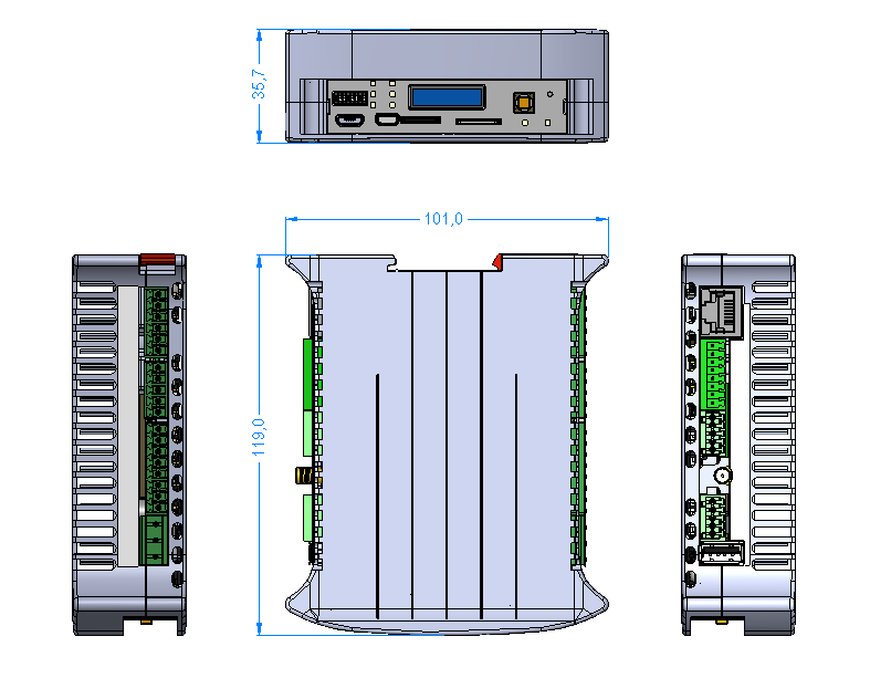
Enclosure
The space that the device occupies can be approximated to a cube of the following dimensions: 119 mm x 101 mm x 35,3 mm.
Norms
EMC standards
| Standard | Title | Description | Comments |
| Emission |
|||
| EN 61000-6-4 | Generic Emission Standard | Emission standard for industrial environment | |
| EN 55011 | Conducted Emission | Limits for Group 1, Class A | Power port |
| EN 55011 | Radiated Emission | Limits for Group 1, Class A | |
| EN 55032 | Conducted Emission | Limits for Class A | Ethernet port |
| Immunity |
|||
| EN 61000-6-2 | Generic Emission Standard | Immunity standard for industrial environment | |
| EN 61000-4-2 | Electrostatic discharge (ESD) | ±4kV (contact discharge), ±8kV (air discharge) | |
| EN 61000-4-3 | Radio Frequency immunity | 10V/m | |
| EN 61000-4-4 | Burst/EFT immunity | ±1kV | All ports |
| EN 61000-4-5 | Surge immunity | ±0.5kV (line-to-line), ±1kV (line-to-earth) | Power port |
| EN 61000-4-29 | Voltage Dips, Short Interruptions and Voltage Variations | In progress | Power port |
Climatic standards
| Standard | Title | Description | Comments |
| EN 61131-2 | Product Standard | Programmable controllers - Part 2: Equipment requirements and tests | |
| EN 60068-2-1 | Cold (storage) | Cold test “storage” suitable for non-heat emitting products. The object of the test is limited to determining the suitability of the components, devices or products for transport or storage at low temperatures. | |
| EN 60068-2-2 | Dry Heat (storage) | Dry heat test “storage” suitable for non-heat emitting products. The object of the test is limited to determining the suitability of the components, devices or products for transport or storage at high temperatures. |
|
| EN 60068-2-1 | Cold (operation) | Cold test “operation” suitable for heat emitting products. The object of the test is limited to determining the suitability of the components, devices or products for operation at low temperatures. | |
| EN 60068-2-2 | Dry Heat (operation) | Dry heat test “operation” suitable for heat emitting products. The object of the test is limited to determining the suitability of the components, devices or products for operation at high temperatures. | |
| EN 60068-2-14 | Change of temperature (storage) | The change of temperature test “storage” is suitable for non-heat emitting products. The objective of this test is limited to determining the suitability of the components, devices, or products for operation during temperature changes. | |
| EN 60068-2-14 | Change of temperature (operation) | The change of temperature test “operation” is suitable for heat emitting products. The objective of this test is limited to determining the suitability of the components, devices, or products for operation during temperature changes. | |
| Redisage | Cold start | Cold start test is suitable for non-heat emitting products just before starting the device. The objective of this test is limited to determining the suitability of the devices for start in cold conditions. | |
| EN 60068-2-30 | Damp Heat (storage) | Damp heat test “storage” is suitable for non-heat emitting products. The objective of this test is limited to determining the suitability of the devices for transport or storage under cyclic damp heat conditions. | |
| EN 60068-2-30 | Damp Heat (operation) | Damp heat test “operation” is suitable for non-heat emitting products. The objective of this test is limited to determining the suitability of the devices for transport or storage under cyclic damp heat conditions. |
Additional notes
Wi-Fi® is a registered trademark of Wi-Fi Alliance®.
| Related information and links |
||
| Ordering information | Accessories | Similar products |
Products family sample photo

DISCLAMER NOTES
ALL PRODUCT, PRODUCT SPECIFICATIONS AND DATA ARE SUBJECT TO CHANGE WITHOUT NOTICE TO IMPROVE RELIABILITY, FUNCTION OR DESIGN OR OTHERWISE.
Datasheet-ID:
TCXV
Get Started
Tiger City IMX Industrial Computer with Linux OS
Connecting Tiger to a power supply
Connect a power supply to the pins shown in the picture below. The suggested power supply is a DC voltage in range of 12-24 V.

Connecting to a console
In order to connect to the system console, follow this instruction.
First boot
In order to perform the first boot, follow this instruction.
Hardware
Introduction
Tiger City IMX Industrial Computer with Linux OS
The Tiger City IMX minicomputer uses Linux operating systems and is equipped with several communication interfaces such as: Ethernet, USB 2.0, HDMI, GSM, RS232, RS485, 1-Wire and multiple analog-digital inputs and outputs. It can also be configured to include a Wi-Fi module and encryption modules that increase the security of the device. The casing enables installation on the DIN rail. The front panel has switches, an OLED display and a joystick for manual control of the device operation.
Specifications of the device
- Power: voltage 12-24 VDC +-20%, maximum power 25 W, reverse polarity protection
- SoM: VAR-SOM-MX8M-MINI
- Core: NXP’s i.MX 8M Mini with 1.6 GHz Quad-core ARM Cortex-A53 and 400 MHz Cortex-M4 real-time processor
- Timing: 1.6 GHz
- RAM: 2 GB DDR4
- Flash eMMC: 16 GB
- 1x microSD connector
- 1x microHDMI 1.3a (optional)
- 1x microUSB 2.0 HOST / OTG, max. 500 mA (optional)
- 1x USB-A 2.0 HOST, max. 1 A
- 1x modem GSM SIM7600E + microSIM (optional)
- 1x 1-Wire (optional)
- 7x DIO - digital input/output, max. 30 V
- 4x UIO - universal analog-digital input/output (temperature measurement with sensors, e.g.: Pt1000, Ni1000, KTY, NTC, current, voltage and resistance sensors), max. 20 V (optional)
- 5x DI - digital input (3 x DI), max. 30 V (optional)
- 2x RS232, baudrate 50-115200 bps
- 2x RS485, baudrate 50-115200 bps (4x optional)
- 1x Ethernet 10/100 Mbps - RJ45 connector
- 1x Wi-Fi® / 2.4G module (optional)
- 1x secure element (optional)
- 1x display OLED 0.87" 128x32 px black&white (optional)
- 1x Joystick (optional)
- RTC (optional), buzzer, EEPROM
- TPM (optional)
- Software watchdog
Dimensions of the device
The space that the device occupies can be approximated to a cube of the following dimensions: 119 mm x 101 mm x 22.5 mm.
Simplified block diagram

Technical Diagrams
Tiger City IMX Industrial Computer with Linux OS
Enclosure
Placement of peripherals
Detailed connections diagram

External Interfaces
Tiger City IMX Industrial Computer with Linux OS
- USB
- Serial ports
- 1-Wire
- HDMI
- ETHERNET
- GSM
- MicroSD slot
- Wi-Fi/2.4G
- Digital inputs
- Digital inputs/outputs
- Universal inputs/outputs
USB
The device is equipped with 2 USB connectors.
USB1
MicroUSB connector for USB 2.0 is placed on the front panel. The interface can work in both host and device modes. The signal on the connector can be changed with a switch. The maximal current of the connector is 500 mA.
MicroUSB connector location

USB1 connection diagram

|
Description |
Processor pin |
Default function |
|
5 V USB voltage |
F22 |
USB1_VBUS |
|
USB data differential pair negative |
A22 |
USB1_D_N |
|
USB data differential pair positive |
B22 |
USB1_D_P |
|
USB on the go |
AB10 |
USB1_OTG_PWR |
UART4
Device name: /dev/ttymxc3
|
Signal |
Processor pin |
Default function |
|
Receive (UART4 RX) |
F19 |
UART4_RXD |
|
Transmit (UART4 TX) |
F18 |
UART4_TXD |
USB2
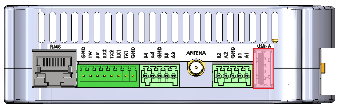
USB-A connector for USB 2.0 is placed on the side of the device with the interface set up in the host mode. The maximal current of the connector is 1 A.
USB-A connector location
USB2 connection diagram

| Description |
Processor pin |
Default function |
|
USB power switch control |
F23 |
USB2_VBUS |
|
USB data differential pair negative |
A23 |
USB2_D_N |
|
USB data differential pair positive |
B23 |
USB2_D_P |
Serial ports
The device is equipped with 3 serial port connectors.
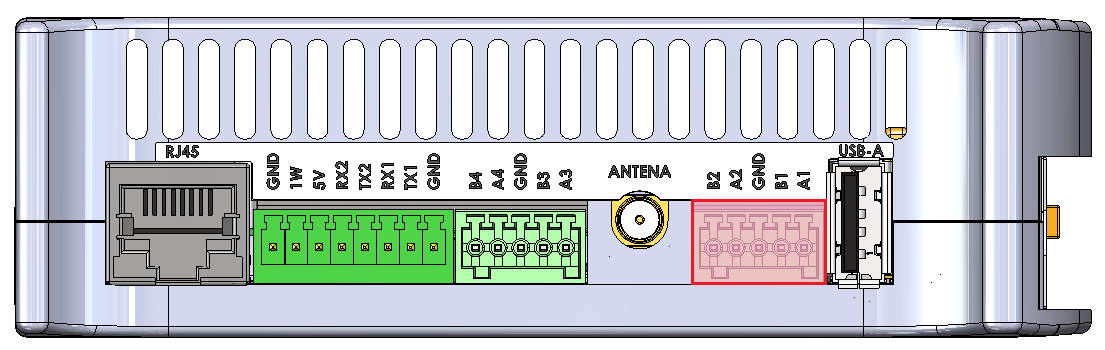
RS485-1/2
Baud rate: 50-115200 bps.
Location of the RS485-1/2 connector
|
Connector pin |
Description |
|
A1 |
RS485 A1 |
|
B1 |
RS485 B1 |
|
G |
Ground |
|
A2 |
RS485 A2 |
|
B2 |
RS485 B2 |
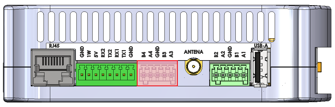
RS485-3/4
Baud rate: 50-115200 bps.
Location of the RS485-3/4 connector
|
Connector pin |
Description |
|
A3 |
RS485 A3 |
|
B3 |
RS485 B3 |
|
G |
Ground |
|
A4 |
RS485 A4 |
|
B4 |
RS485 B4 |
RS485-1/2/3/4 connections diagram

//sprawdzić z Dmytro całkowitą rezystancję terminacji (rezystor + transoptor go załączający)
SPI2
|
Signal |
Processor pin |
Default function |
|
Chip select 0 |
A6 |
SPI2_CS0 |
|
Chip select 1 |
AF12 |
SPI2_CS1 |
|
Chip select 2 |
AB19 |
SPI2_CS2 |
|
Master in slave out |
A8 |
SPI2_MISO |
|
Clock |
E6 |
SPI2_SCLK |
|
Master out slave in |
B8 |
SPI2_MOSI |
Expander B
The RS485 1 & 2 lines are controlled from the B expander connected by the SPI2 interface with the CPU.
Expander F
The RS485 3 & 4 lines are controlled from the F expander connected by the SPI2 interface with the CPU.
Expander E
The termination resistors are controlled by signals output from the Expander E connected by the I2C3 interface with the CPU.
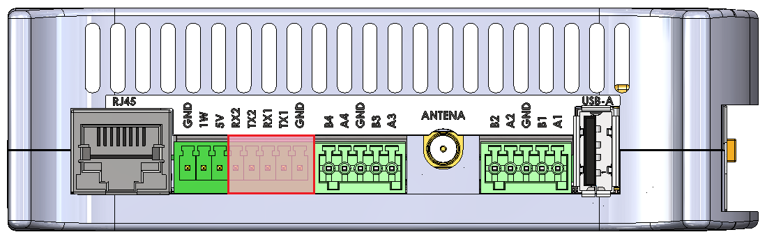
RS232-1/2
Baud rate: 50-115200 bps.
Location of the RS232-1/2 connector
|
Connector pin |
Description |
|
T1 |
RS232 TX1 |
|
R1 |
RS232 RX1 |
|
G |
Ground |
|
T2 |
RS232 TX2 |
|
R2 |
RS232 RX2 |
RS232-1/2 connections diagram

UART4
Device name: /dev/ttymxc3
|
Signal |
Processor pin |
Default function |
|
Receive (UART4 RX) |
F19 |
UART4_RXD |
|
Transmit (UART4 TX) |
F18 |
UART4_TXD |
UART1
Device name: /dev/ttymxc0
|
Signal |
Processor pin |
Default function |
|
Receive (UART1 RX) |
E14 |
UART1_RXD |
|
Transmit (UART1 TX) |
F13 |
UART1_TXD |
UART3
Device name: /dev/ttymxc2
|
Signal |
Processor pin |
Default function |
|
Receive (UART3 RX) |
E18 |
UART3_RXD |
|
Transmit (UART3 TX) |
D18 |
UART3_TXD |
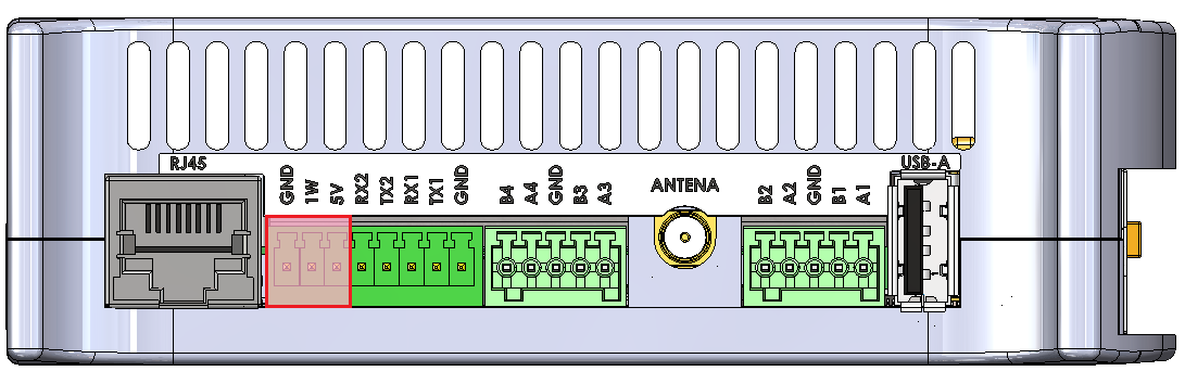
1-Wire
The device is equipped with the 1-Wire interface operating with Maxim sensors. Connector 5 V outputs are secured with a 100 mA fuse.
1-Wire connector and pins
| Connector pin |
Description |
|
1W |
1-Wire data |
|
5V |
1-Wire +5 V power |
|
G |
Ground |
1-Wire connection diagram

I2C2
Device name: /dev/i2c-1
|
Signal |
Processor pin |
Default function |
|
Clock |
D10 |
I2C2_SCL |
|
Data |
D9 |
I2C2_SDA |
1-Wire bridge
Part number: DS2484
HDMI
The device is equipped with the micro HDMI standard connector located on the front panel.
HDMI connector location

|
Signal |
Processor pin |
Default function |
|
DSI_TX0_N |
A9 |
MIPI_DSI_TX0_N |
|
DSI_TX0_P |
B9 |
MIPI_DSI_TX0_P |
|
DSI_TX1_N |
A10 |
MIPI_DSI_TX1_N |
|
DSI_TX1_P |
B10 |
MIPI_DSI_TX1_P |
|
DSI_TX2_N |
A12 |
MIPI_DSI_TX2_N |
|
DSI_TX2_P |
B12 |
MIPI_DSI_TX2_P |
|
DSI_TX3_N |
A13 |
MIPI_DSI_TX3_N |
|
DSI_TX3_P |
B13 |
MIPI_DSI_TX3_P |
|
DSI_CLK_N |
A11 |
MIPI_DSI_CLK_N |
|
DSI_CLK_P |
B11 |
MIPI_DSI_CLK_P |
HDMI connection diagram

DSI/HDMI Bridge
Part number: LT8912B
I2C4
Device name: /dev/i2c-3
|
Signal |
Processor pin |
Default function |
|
Clock |
D13 |
I2C4_SCL |
|
Data |
E13 |
I2C4_SDA |
I2C2
Device name: /dev/i2c-1
|
Signal |
Processor pin |
Default function |
|
Clock |
D10 |
I2C2_SCL |
|
Data |
D9 |
I2C2_SDA |
ETHERNET
The device is equipped with a RJ45 connector placed on the side of the device. The diode on the front panel indicates ETHERNET's operation.
RJ45 connector location
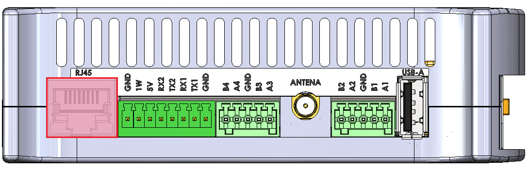
ETHERNET connection diagram

GSM
The device is equipped with the SIM7600E module connected with the miniPCIE connector. Its features:
- operation of protocols: CP, UDP, PPP, HTTP, FTP, MQTT, SMS, Mail
- GNSS (GPS, GLONASS, BeiDou) positioning
- the microSIM card can be installed
- the device can be expanded with an antenna
- LED on the front panel indicates GSM operation
Device name: SIM7600E
MicroSIM connector
|
Function |
Processor pin |
Default function |
|
USB power switch control |
F23 |
USB2_VBUS |
|
USB data differential pair negative |
A23 |
USB2_D_N |
|
USB data differential pair positive |
B23 |
USB2_D_P |
GSM connection diagram

USB HUB
Part number: USB2533I-1080AEN
I2C4
Device name: /dev/i2c-3
|
Signal |
Processor pin |
Default function |
|
Clock |
D13 |
I2C4_SCL |
|
Data |
E13 |
I2C4_SDA |
MicroSD slot
The device is equipped with a microSD card slot, connected directly to the CPU.


|
Function |
Processor pin |
Default function |
| SD data line 0 | AB23 | SD2_DATA0 |
| SD data line 1 | AB24 | SD2_DATA1 |
| SD data line 2 | V24 | SD2_DATA2 |
| SD data line 3 | V23 | SD2_DATA3 |
| SD command line | W24 | SD2_CMD |
| SD clock | W23 | SD2_CLK |
Wi-Fi/2.4G
The SOM is equipped with a Wi-Fi/2.4G module and can be connected to the dedicated IPX antenna connector or expanded with a Wi-Fi antenna which takes the place of digital inputs no. 1 and 2. The module is dual-band and operates on the frequencies of 2.4 and 5 GHz in 802.11.ac/a/b/g/n standard. The antennas can also be connected directly to the GSM module depending on the current needs.
Wi-Fi connections diagram

Wi-Fi module
Part number: Sterling-LWB5
Digital inputs
The device is equipped with a 5-pin digital inputs (DI) connector with a maximum voltage of 30 V and a dry contact. Input signals connect directly to the CPU.
DIs location on the connector
|
DI connector pin |
Processor pin |
User-space name |
|
|
DI1 |
AC22 |
gpiochip3 26 |
"DI1" |
|
DI2 |
AD23 |
gpiochip3 24 |
"DI2" |
|
DI3 |
AB22 |
gpiochip3 22 |
"DI3" |
|
DI4 |
AD15 |
gpiochip2 25 |
"DI4" |
|
DI5 |
AC13 |
gpiochip2 24 |
"DI5" |
DI circuit block schematic

- R1 - push-up resistor 47 kΩ
Digital inputs/outputs
The device is equipped with 7 digital input/output (DIO) connectors. They can operate as:
- digital input with a maximal voltage of 30 V and a dry contact
- digital Vin output with a maximal current of 200 mA
DIOs location on the connector
|
DIO connector pin |
Input |
Output |
||
|
User-space name |
Expander E pin |
User-space name |
Expander A pin |
|
|
DIO1 |
gpiochip5 9 |
24 |
gpiochip7 1 |
1 |
|
DIO2 |
gpiochip5 10 |
25 |
gpiochip7 2 |
2 |
|
DIO3 |
gpiochip5 11 |
28 |
gpiochip7 3 |
3 |
|
DIO4 |
gpiochip5 12 |
1 |
gpiochip7 4 |
4 |
|
DIO5 |
gpiochip5 13 |
2 |
gpiochip7 5 |
5 |
|
DIO6 |
gpiochip5 14 |
3 |
gpiochip7 6 |
6 |
|
DIO7 |
gpiochip5 15 |
4 |
gpiochip7 7 |
7 |
DIO circuit block schematic

- F1 - 200 mA fuse
- R1 - pull-up resistor 10 kΩ
- R2 - pull-up resistor 47 kΩ
Expander E
The circuit's inputs are connected to the expander E via the I2C3 interface.
Expander A
Outputs of the circuit are connected to the expander A via the SPI1 interface.
Universal inputs/outputs
The device is equipped with 4 universal analog-digital inputs/outputs (UIOs). They can operate as:
- DC voltage inputs for voltage in the range of 0-10 V with the input resistance of 100 kΩ
- current inputs for current in the range of 0-4-20 mA with the input resistance of 200 Ω
- current outputs with the range of 4-20 mA
- temperature inputs of sensors: Pt1000, Ni1000, KTY, NTC
- resistance inputs with the range of 0-5000 Ω
- dry contact inputs
- analog to digital converters with 24-bit resolution
- digital to analog converters with 12-bit resolution
Voltage is measured using a 2-channel analog-to-digital converter with 24-bit resolution.
A current value can be set using a 4-channel digital-to-analog converter.
UIOs location on the connector
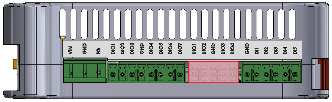
Diagram of UIO circuit

- R1 - 200 Ω/1% measurement resistor
- R2 - 100 kΩ/1% measurement resistor
- R3 - switchable resistor for changing range of current sources (649 Ω/1% or 1,649 Ω/1%)
User-space access
Analog-Digital Converter A Device name: /sys/bus/iio/devices/iio:device0
Analog-Digital Converter B Device name: /sys/bus/iio/devices/iio:device1
Digital-Analog Converter A Device name: /sys/bus/iio/devices/iio:device2
Possible configurations
Switching to particular modes of the circuit is realized by “Set voltage input”, “Set current input”, “Current enable”, “Set R3 resistance value” and “Set current value” signals.
|
Configuration signal |
Modes of operation |
|||
|---|---|---|---|---|
|
DI dry contact |
AI 0-10 V |
AI 0-4-20 mA |
AO 4-20 mA / temperature* / resistance |
|
|
Set voltage input |
0 |
1 |
0 |
0 |
|
Set current input |
0 |
1 |
0 |
1 |
|
Current enable |
1 |
0 |
0 |
1 |
|
Set R3 resistance value |
1 |
X |
X |
1 or 0** |
|
Set current value |
12-bit value*** |
X |
X |
12-bit value*** |
* by measuring resistance
** 1 for 1,649 kΩ/1% or 0 for 649 Ω/1% resistor
*** depends on the sensor (see examples for more)
- X - any value
- DI - digital input
- AI - analog input
- AO - analog output
|
UIO connector pin |
Configuration signal |
Expander C pin |
|
UIO1 |
Current enable |
20 |
|
Set voltage input |
19 |
|
|
Set current input |
27 |
|
|
Set R3 resistance value |
21 |
|
|
UIO2 |
Current enable |
3 |
|
Set voltage input |
22 |
|
|
Set current input |
28 |
|
|
Set R3 resistance value |
4 |
|
|
UIO3 |
Current enable |
23 |
|
Set voltage input |
17 |
|
|
Set current input |
1 |
|
|
Set R3 resistance value |
18 |
|
|
UIO4 |
Current enable |
26 |
|
Set voltage input |
24 |
|
|
Set current input |
2 |
|
|
Set R3 resistance value |
25 |
Expander C
The circuit's inputs are connected to the expander C via the I2C2 interface.
I2C3
Device name: /dev/i2c-2
|
Signal |
Processor pin |
Default function |
|
Clock |
E10 |
I2C3_SCL |
|
Data |
F10 |
I2C3_SDA |
I2C2
Device name: /dev/i2c-1
|
Signal |
Processor pin |
Default function |
|
Clock |
D10 |
I2C2_SCL |
|
Data |
D9 |
I2C2_SDA |
Internal Devices
Tiger City IMX Industrial Computer with Linux OS
- Internal expansion connector
- Watchdog + reset
- EEPROM
- FLASH
- RTC
- ESP32 microcontroller
- TPM 2.0
- Secure element TO136
- Buzzer
Internal expansion connector
Part number: FH1234-221CWG0MUT01
Internal expansion connector connections diagram

Internal expansion connector connections table
|
Connector pin |
Description |
|
1 |
GND |
|
2 |
VIN |
|
3 |
GND |
|
4 |
SPI1 MOSI |
|
5 |
GND |
|
6 |
SPI1 SCLK |
|
7 |
GND |
|
8 |
SPI1 MISO |
|
9 |
GND |
|
10 |
RTC battery power supply |
|
11 |
External watchdog reset |
|
12 |
NC |
|
13 |
GND |
|
14 |
NC |
|
15 |
NC |
|
16 |
NC |
|
17 |
GPIO4 IO25 |
|
18 |
GND |
|
19 |
GPIO1 IO07 |
|
20 |
GPIO4 IO21 |
|
21 |
GPIO5 IO09 |
|
22 |
Global reset |
|
23 |
GND |
|
24 |
I2C3 SDA |
|
25 |
I2C3 SCL |
|
26 |
GND |
|
27 |
+3V3 |
|
28 |
GND |
|
29 |
USB3 positive pole |
|
30 |
USB3 negative pole |
|
31 |
GND |
|
32 |
+20V |
|
33 |
UIO reset |
|
34 |
NC |
|
35 |
NC |
|
36 |
+1V8 |
|
37 |
+1V8 |
|
38 |
GND |
|
39 |
+5V |
|
40 |
+5V |
|
41 |
GND |
|
42 |
GND |
|
43 |
VIN |
|
44 |
GND |
Watchdog + reset
The device is equipped with a watchdog and a reset circuit.
Watchdog and reset circuit connections diagram

CPU connections table
|
Signal |
Default function |
User-space name |
|
|
ESP32_WDI |
GPIO1_IO01 |
gpiochip0 1 |
ESP32_WDI |
|
SOM_GLOB_NRST |
GPIO5_IO02 |
gpiochip4 2 |
GLOBAL_NRST |
|
GPIO0 |
GPIO3_IO22 |
gpiochip2 22 |
ESP_GPIO0 |
|
GPIO2 |
GPIO3_IO20 |
gpiochip2 20 |
ESP_GPIO2 |
|
ESP_CHIP_PU |
GPIO4_IO20 |
gpiochip3 20 |
ESP_CHIP_PU |
ESP32 reset
The device is equipped with an ESP32 microcontroller as a watchdog.
EEPROM
The device is equipped with 2 EEPROM memory modules. EEPROM B is read-only and reserved for the producer's purposes.
EEPROM device
Part number: M24C02-RMC6
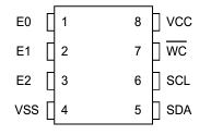
EEPROM A connections table
|
EEPROM pin |
Description |
User-space name |
|
1 |
Address pin 0 (GND) |
X |
|
2 |
Address pin 1 (+3V3) |
X |
|
3 |
Address pin 2 (+3V3) |
X |
|
5 |
I2C2 data |
X |
|
6 |
I2C2 clock |
X |
|
7 |
EEPROM write-protect |
gpiochip0 2 |
EEPROM B (EEPROM SN) connections table
|
EEPROM pin |
Description |
User-space name |
|
1 |
Address pin 0 (GND) |
X |
|
2 |
Address pin 1 (+3V3) |
X |
|
3 |
Address pin 2 (GND) |
X |
|
5 |
I2C2 data |
X |
|
6 |
I2C2 clock |
X |
|
7 |
EEPROM write-protect (pull-up) |
X |
EEPROM connection diagram

User-space access
EEPROM device name: /sys/bus/nvmem/devices/1-00561
EEPROM device address: 0x56
I2C2
EEPROMs A and B are connected to the CPU with the I2C2 interface.
FLASH
Part number: W25Q64JVSSIQ
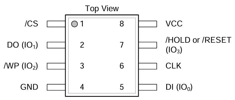
FLASH connections table
|
FLASH pin |
Description |
User-space name |
|
1 |
SPI1_CS0 |
gpiochip2 21 |
|
2 |
SPI1_MISO |
X |
|
3 |
SPI1_WP |
X |
|
5 |
SPI1_MOSI |
X |
|
6 |
SPI1_SCLK |
X |
|
7 |
SPI1_HOLD |
X |
FLASH connection diagram

User-space access
FLASH device name: /dev/mtdblock0
SPI1
FLASH is connected to the CPU with the SPI1 interface.
RTC
The device is equipped with a real-time clock operating at 32.768 kHz with a tolerance of 20 ppm. The RTC clock is connected to a DR2032 battery which serves as its power supply.
RTC device
Part number: DS1338
RTC connection diagram

User-space access
Device name: /sys/class/rtc/rtc0
Device address: 0x68
RTC connections table
|
RTC pin |
Description |
|
1 |
Clock oscillator pin no. 1 |
|
2 |
Clock oscillator pin no. 2 |
|
3 |
Battery power pin |
|
5 |
I2C3 data |
|
6 |
I2C3 clock |
I2C3
The real-time clock is connected to the CPU with the I2C3 interface.
ESP32 microcontroller
The device is equipped with an internal ESP32 microcontroller that can be used for internal purposes.
ESP32 device
Part number: ESP32-DOWD
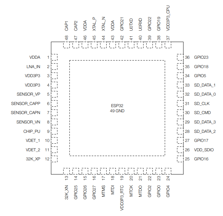
ESP32 connections table
|
ESP32 pin |
Description |
|
8 |
ESP_P_DETECT |
|
9 |
ESP_CHIP_PU |
|
14 |
ESP32_WDT_EN |
|
15 |
ESP32_WDI |
|
22 |
ESP_GPIO2 |
|
23 |
ESP_GPIO0 |
|
24 |
RESET_WDT |
|
25 |
LED_ESP |
|
26 |
VDD_SDIO |
|
28 |
ESP_SPI_HD |
|
29 |
ESP_SPI_WP |
|
30 |
ESP_SPI_CS0 |
|
31 |
ESP_SPI_CLK |
|
32 |
ESP_SPI_Q |
|
33 |
ESP_SPI_D |
|
38 |
I2C4_SCL |
|
39 |
I2C4_SDA |
|
40 |
ESP_CONSOLE_RX |
|
41 |
ESP_CONSOLE_TX |
ESP32 connections diagram

CPU connections table
|
Signal |
CPU pin |
Default function |
User-space name |
|
ESP_GPIO_0 |
AC14 | GPIO3_IO22 | gpiochip2 22 |
| ESP_GPIO_2 | AC15 | GPIO3_IO20 | gpiochip2 20 |
|
ESP32_WDI |
AF14 | GPIO1_IO01 | gpiochip0 1 |
|
ESP32_WDT_EN |
AF13 |
GPIO1_IO03 |
gpiochip0 3 |
I2C4
The microcontroller is connected to the CPU via the I2C4 interface.
UART3
The microcontroller is connected to the CPU via the UART3 interface.
TPM 2.0
The device is equipped with a trusted platform module in 2.0 standard.
TPM device
Part number: SLM9670
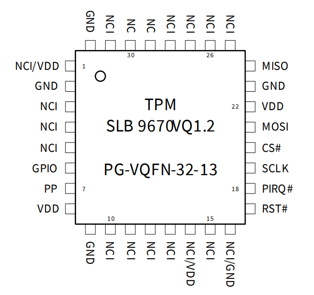
TPM connections table
|
TPM pin |
Description |
|
17 |
Reset |
|
18 |
TPM_IRQ |
|
19 |
SPI2 clock |
|
20 |
SPI2 chip select 0 |
|
21 |
SPI2 master out slave in |
|
24 |
SPI2 master in slave out |
User-space access
Device name: /sys/class/tpm
TPM connection diagram

CPU connections table
|
Signal |
CPU pin |
Default function |
User-space name |
|
TPM_IRQ |
AC24 |
GPIO4_IO23 |
gpiochip3 23 |
|
SPI2_CS0_TPM |
A6 |
GPIO5_IO13 |
gpiochip4 13 |
SPI2
The trusted platform module is connected to the CPU with the SPI2 interface.
Secure element TO136
The device is equipped with a secure element that can be used for data encoding.
Secure element device
Part number: IDEMIA TO136
Secure element connections table
|
Secure element pin |
Description |
|
1 |
I2C4 clock |
|
2 |
I2C4 data |
|
3 |
+3V3 |
|
6 |
IDLE/BUSY state report |
User-space access
Device address: 0x50
Secure element connections diagram

Expander E
The secure element is connected to the Expander E connected to the CPU via the I2C3 interface.
I2C4
The secure element is connected to the CPU via the I2C4 interface.
Buzzer
The device is equipped with a buzzer.
Buzzer device
Part number: LD-BZEG-0905
User-space access
Device name: gpiochip3 7
Label: "BUZZER"
Buzzer connection diagram

Front Panel
Tiger City IMX Industrial Computer with Linux OS
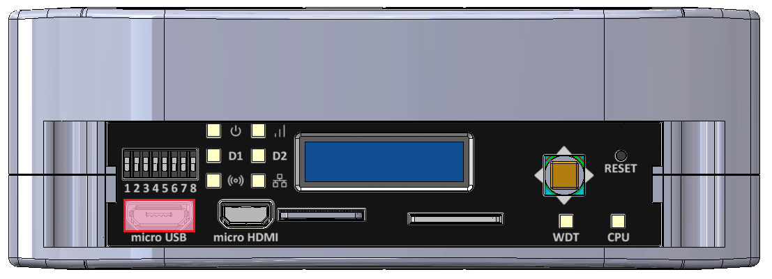
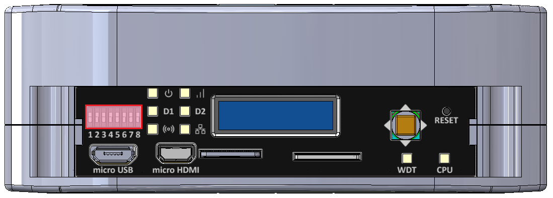
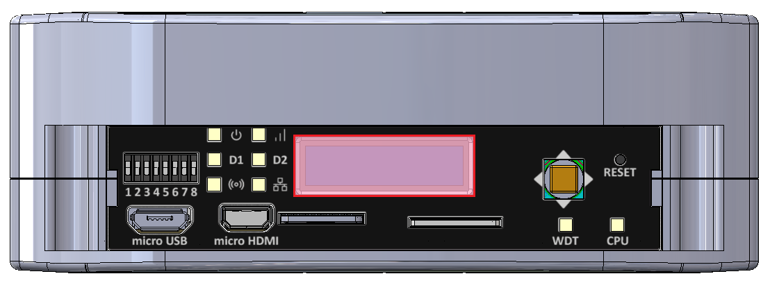
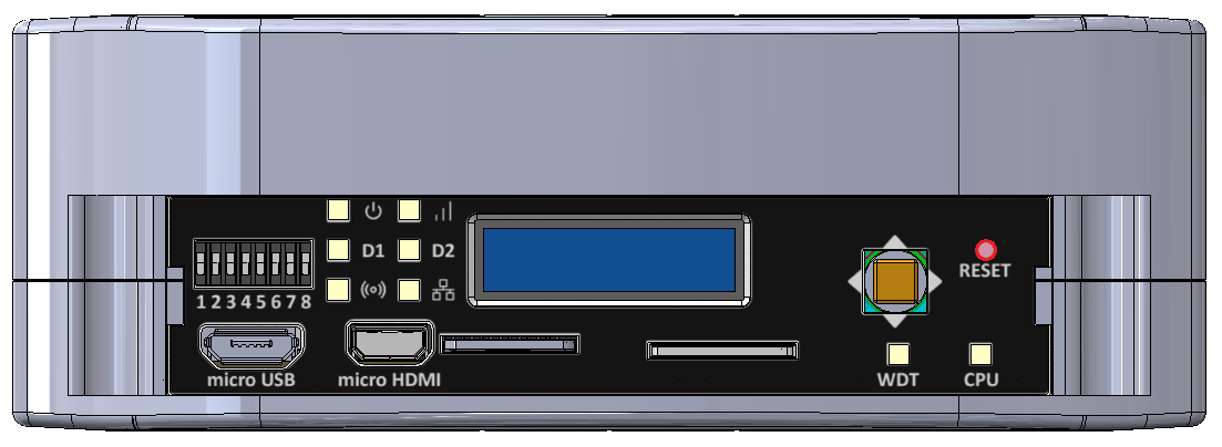
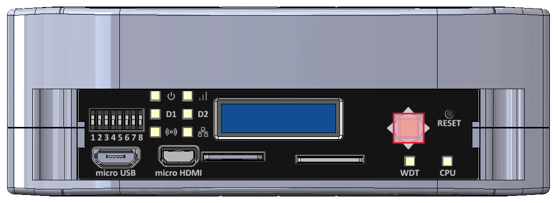
View of the front panel
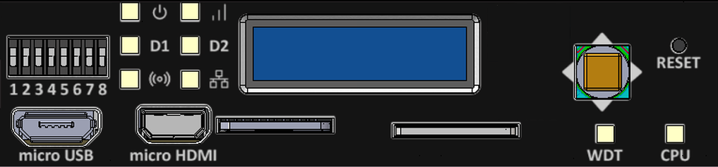
Components of the front panel
DIP switches
The device has DIP switches on the front panel which enable the control of various key functions such as:
- booting mode choice
- microUSB signal choice
- choosing Linux console or RS232 signal
- user-written code
DIP switches placement on the front panel
Switch options
|
Switch No. |
Positions |
Description |
|
1 |
OFF - eMMC boot ON - SD card boot |
Boot select - switching between booting device |
|
2 |
OFF - USB1 OTG ON - UART4 (Linux console) |
USB select - microUSB signal choice |
|
3 |
OFF - UART1 (SOM user) ON - UART4 (Linux console) |
RS232 - SOM UART RS232 select |
|
4 |
OFF - UART2 RS232 user ON - ESP32 console |
RS232 - SOM UART RS232/ESP32 select |
|
5 |
Unassigned |
Currently not used |
|
6-8 |
OFF/ON |
User options |
Connections diagram

Expander D
User-defined DIP switch options are connected to the expander D which is connected to the CPU via the I2C3 interface.
USB1
The USB MUX select 1 and the USB MUX select 2 signals are connected to the multiplexer A associated with USB1.
Signal LEDs
The device is equipped with 8 LEDs. 2 of these LEDs are placed on the mainboard, while the other 6 are on the front panel of the HMI board.
LEDs location
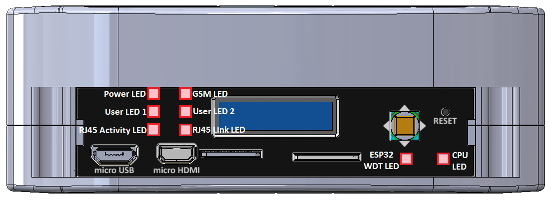
LEDs connections
|
Description |
User-space name |
Label |
| Power LED |
gpiochip6 9 |
"LED_5V" |
| CPU LED |
gpiochip0 3 |
"LED_MAINBOARD" |
|
User LED 1 G |
gpiochip6 10 |
"LED3_GREEN" |
|
User LED 1 R |
gpiochip6 5 |
"LED3_RED" |
|
User LED 1 B |
gpiochip6 12 |
"LED3_BLUE" |
|
User LED 2 G |
gpiochip6 13 |
"LED4_GREEN" |
|
User LED 2 R |
gpiochip6 11 |
"LED4_RED" |
|
User LED 2 B |
gpiochip6 15 |
"LED4_BLUE" |
LED connection diagram

ESP32 microcontroller
ESP LED is connected directly to the ESP32 microcontroller.
GSM
GSM LED is connected directly to the GSM modem.
ETHERNET
ETH activity LED and ETH link LED are connected directly to the ETHERNET physical layer.
Expander D
Power LED, User LED 1 and User LED2 are connected to the expander D which is connected to the CPU via the I2C3 interface.
OLED display
The device is equipped with a 0.87” black and white display with a resolution of 128x32 px.
OLED display placement
OLED device
Part number: SCE087002-V01
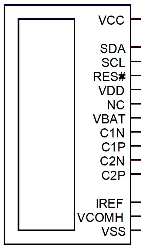
OLED connections table
|
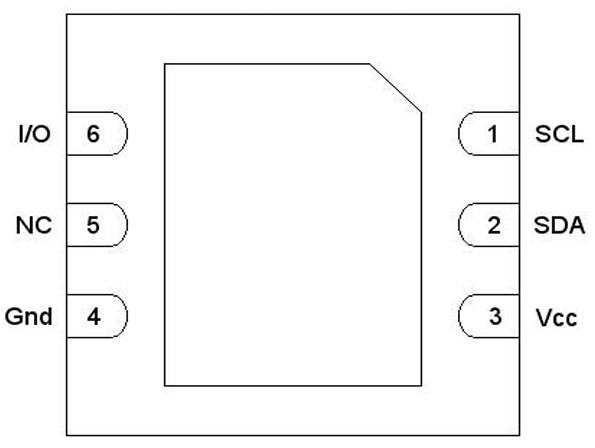
OLED pin |
Description |
User-space name |
|
RES# |
RESET |
X |
|
SCL |
I2C3 clock |
X |
|
SDA |
I2C3 data |
X |
|
VCC |
OLED ON/OFF |
gpiochip6 14, "OLED_EN" |
OLED connections diagram

Expander D
The OLED display is connected to Expander D which is connected to the CPU via the I2C3 interface.
I2C3
The OLED display is directly connected to the CPU via the I2C3 interface.
Joystick
The device is equipped with a joystick for controlling its functions.
Placement

Device
Part number: INT-1500D
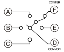
Connections table
|
Joystick signal |
Expander D pin |
User-space name |
Label |
|
Right |
20 |
gpiochip6 3 |
"JOY_RIGHT" |
|
Up |
18 |
gpiochip6 1 |
"JOY_UP" |
|
Left |
17 |
gpiochip6 0 |
"JOY_LEFT" |
|
Down |
19 |
gpiochip6 2 |
"JOY_DOWN" |
|
Push |
21 |
gpiochip6 4 |
"JOY_PUSH" |
Connection diagram

Expander D
Joystick is connected to the Expander D which is connected to the CPU via the I2C3 interface.
Reset button
The device has a reset button on the front panel.
Reset button location
Connections diagram

Watchdog + reset
Expanders
Tiger City IMX Industrial Computer with Linux OS
Expander A
Part number: 74HC595BQ
Expander A diagram
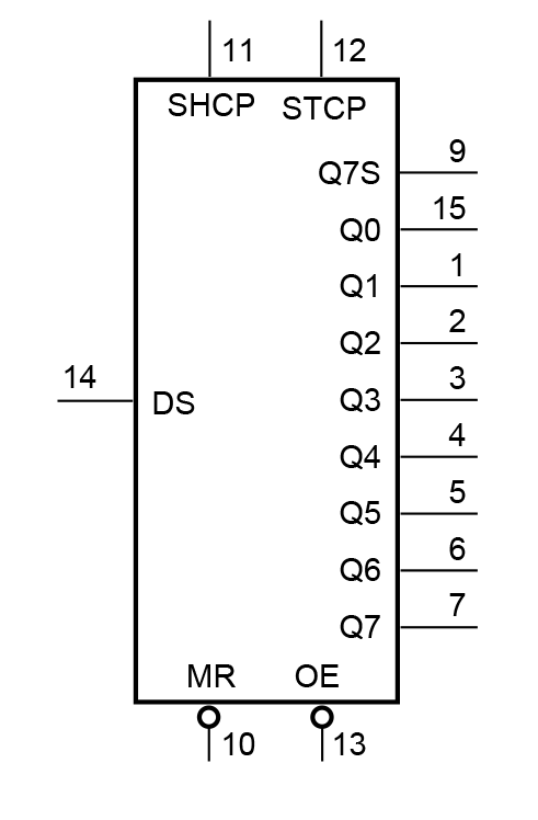
Expander A pins description
|
Pin |
Type |
Usage |
User-space name |
Description |
|
1 |
Q1 |
DO1 |
gpiochip8 1 |
Digital output 1 |
|
2 |
Q2 |
DO2 |
gpiochip8 2 |
Digital output 2 |
|
3 |
Q3 |
DO3 |
gpiochip8 3 |
Digital output 3 |
|
4 |
Q4 |
DO4 |
gpiochip8 4 |
Digital output 4 |
|
5 |
Q5 |
DO5 |
gpiochip8 5 |
Digital output 5 |
|
6 |
Q6 |
DO6 |
gpiochip8 6 |
Digital output 6 |
|
7 |
Q7 |
DO7 |
gpiochip8 7 |
Digital output 7 |
|
9 |
Q7S |
NC |
X |
Not connected |
|
10 |
MR/ |
NRST_GLOBAL |
X |
Reset |
|
11 |
SHCP |
SPI1_SCLK |
X |
SPI clock |
|
12 |
STCP |
SPI1_CS1 |
X |
SPI chip select |
|
13 |
OE/ |
GND |
X |
Output enable |
|
14 |
DS |
SPI1_MOSI |
X |
SPI master out slave in |
|
15 |
Q0 |
MUX_DIO_SEL |
gpiochip8 0 |
MUX_PWM selection signal |
|
16 |
VCC |
+3V3 |
X |
Power supply |
SPI1
|
Signal |
Processor pin |
Default function |
|
Chip select 0 |
AD18 |
SPI1_CS0 |
|
Chip select 1 |
AG23 |
SPI1_CS1 |
|
Master in slave out |
A7 |
SPI1_MISO |
|
Clock |
D6 |
SPI1_SCLK |
|
Master out slave in |
B7 |
SPI1_MOSI |
Expander B
Part number: SC16IS752IBS
Expander B diagram
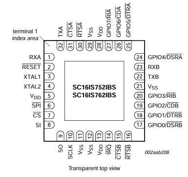
Expander B pins description
|
Pin |
Type |
Usage |
User-space name |
Description |
|
1 |
RXA(I) |
RS485_UART1_RX |
X |
RS485 UART1 RX |
|
2 |
RESET/ |
RS485_NRST |
X |
Reset |
|
3 |
XTAL1(I) |
TXCO_OUT |
X |
Oscillator output |
|
4 |
XTAL2(O) |
NC |
X |
Not connected |
|
5 |
VDD |
+3V3 |
X |
Power supply |
|
6 |
I2C / SPI/ |
GND |
X |
Ground |
|
7 |
CS/ / A0 |
SPI2_CS1 |
X |
SPI chip select |
|
8 |
SI / A1 |
SPI2_MOSI |
X |
SPI master out slave in |
|
9 |
SO |
SPI2_MISO |
X |
SPI master in slave out |
|
10 |
SCL / SCLK |
SPI2_SCLK |
X |
SPI clock |
|
11 |
SDA / VSS |
GND |
X |
Ground |
|
12 |
VSS |
GND |
X |
Ground |
|
14 |
IRQ/ |
RS485_INT |
X |
RS485 interrupt |
|
15 |
CTSB/ |
NC |
X |
Not connected |
|
16 |
RTSB/ |
RS485_UART2_RTS |
X |
RS485 UART2 RTS |
|
17 |
GPIO0 / DSRB/ |
NC |
X |
Not connected |
|
18 |
GPIO1 / DTRB/ |
NC |
X |
Not connected |
|
19 |
GPIO2 / CDB/ |
NC |
X |
Not connected |
|
20 |
GPIO3 / RIB/ |
NC |
X |
Not connected |
|
22 |
TXB(O) |
RS485_UART2_TX |
X |
RS485 UART2 TX |
|
23 |
RXB(I) |
RS485_UART2_RX |
X |
RS485 UART2 RX |
|
24 |
GPIO4 / DSRA/ |
NC |
X |
Not connected |
|
25 |
GPIO5 / DTRA/ |
NC |
X |
Not connected |
|
26 |
GPIO6 / CDA/ |
NC |
X |
Not connected |
|
27 |
GPIO7 / RIA/ |
NC |
X |
Not connected |
|
30 |
RTSA/ |
RS485_UART1_RTS | X | RS485 UART1 RTS |
|
31 |
CTSA/ |
NC |
X |
Not connected |
|
32 |
TXA(O) |
RS485_UART1_TX |
X |
RS485 UART1 TX |
SPI2
|
Signal |
Processor pin |
Default function |
|
Chip select 0 |
A6 |
SPI2_CS0 |
|
Chip select 1 |
AF12 |
SPI2_CS1 |
|
Chip select 2 |
AB19 |
SPI2_CS2 |
|
Master in slave out |
A8 |
SPI2_MISO |
|
Clock |
E6 |
SPI2_SCLK |
|
Master out slave in |
B8 |
SPI2_MOSI |
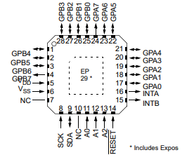
Expander C
Part number: MCP23017-E/ML
Expander C diagram

Expander C pins description
|
Pin |
Port |
Type |
User-space name |
Description |
|
1 |
GPB4 |
GPIO |
gpiochip5 12 |
UIO4 voltage |
|
2 |
GPB5 |
GPIO |
gpiochip5 13 |
UIO4 current |
|
3 |
GPB6 |
GPIO |
gpiochip5 14 |
UIO4 resistance |
|
4 |
GPB7 |
GPIO |
gpiochip5 15 |
UIO3 resistance |
|
5 |
VDD |
+3V3 |
X |
Power supply |
|
6 |
VSS |
GND |
X |
Ground |
|
7 |
NC |
NC |
X |
Not connected |
|
8 |
SCK |
GPIO |
X |
I2C clock |
|
9 |
SDA |
GPIO |
X |
I2C data |
|
10 |
NC |
NC |
X |
Not connected |
|
11 |
A0 |
GND |
X |
Address bit 0 |
|
12 |
A1 |
GND |
X |
Address bit 1 |
|
13 |
A2 |
GND |
X |
Address bit 2 |
|
14 |
RESET/ |
EXP2_NRST |
X |
Reset |
|
15 |
INTB |
NC |
X |
Not connected |
|
16 |
INTA |
NC |
X |
Not connected |
|
17 |
GPA0 |
GPIO |
gpiochip5 0 |
UIO2 resistance |
|
18 |
GPA1 |
GPIO |
gpiochip5 1 |
UIO1 resistance |
|
19 |
GPA2 |
GPIO |
gpiochip5 2 |
UIO1 voltage |
|
20 |
GPA3 |
GPIO |
gpiochip5 3 |
UIO2 voltage |
|
21 |
GPA4 |
GPIO |
gpiochip5 4 |
UIO3 voltage |
|
22 |
GPA5 |
GPIO |
gpiochip5 5 |
UIO1 current |
|
23 |
GPA6 |
GPO |
gpiochip5 6 |
UIO4 I source |
|
24 |
GPA7 |
GPIO |
gpiochip5 7 |
UIO3 current |
|
25 |
GPB0 |
GPIO |
gpiochip5 8 |
UIO2 current |
|
26 |
GPB1 |
GPO |
gpiochip5 9 |
UIO1 I source |
|
27 |
GPB2 |
GPO |
gpiochip5 10 |
UIO2 I source |
|
28 |
GPB3 |
GPO |
gpiochip5 11 |
UIO3 I source |
I2C2
Device name: /dev/i2c-1
|
Signal |
Processor pin |
Default function |
|
Clock |
D10 |
I2C2_SCL |
|
Data |
D9 |
I2C2_SDA |
Expander D
Part number: MCP23017
Expander D diagram
Expander D pins description
|
Pin |
Port |
Type |
User-space name |
Description |
|
1 |
GPB4 |
GPO |
gpiochip6 12 |
LED3 BLUE ON / OFF |
|
2 |
GPB5 |
GPO |
gpiochip6 13 |
LED4 GREEN ON / OFF |
|
3 |
GPB6 |
GPO |
gpiochip6 14 |
OLED ON / OFF |
|
4 |
GPB7 |
GPO |
gpiochip6 15 |
LED4 BLUE ON / OFF |
|
5 |
VDD |
+3V3 |
X |
Power supply |
|
6 |
VSS |
GND |
X |
Ground |
|
7 |
NC1 |
NC |
X |
Not connected |
|
8 |
SCK |
GPIO |
X |
I2C clock |
|
9 |
SDA |
GPIO |
X |
I2C data |
|
10 |
NC2 |
NC |
X |
Not connected |
|
11 |
A0 |
GND |
X |
Address bit 0 |
|
12 |
A1 |
GND |
X |
Address bit 1 |
|
13 |
A2 |
GND |
X |
Address bit 2 |
|
14 |
RESET/ |
NRST_GLOBAL |
X |
Reset |
|
15 |
INTB |
HMI_IRQ |
X |
Interrupt B |
|
16 |
INTA |
HMI_IRQ |
X |
Interrupt A |
|
17 |
GPA0 |
GPI |
gpiochip6 0 |
Joystick left input |
|
18 |
GPA1 |
GPI |
gpiochip6 1 |
Joystick up input |
|
19 |
GPA2 |
GPI |
gpiochip6 2 |
Joystick down input |
|
20 |
GPA3 |
GPI |
gpiochip6 3 |
Joystick right input |
|
21 |
GPA4 |
GPI |
gpiochip6 4 |
Joystick push input |
|
22 |
GPA5 |
GPO |
gpiochip6 5 |
LED3 RED ON / OFF |
|
23 |
GPA6 |
GPI |
gpiochip6 6 |
DIP switch 6 input |
|
24 |
GPA7 |
GPI |
gpiochip6 7 |
DIP switch 7 input |
|
25 |
GPB0 |
GPI |
gpiochip6 8 |
DIP switch 8 input |
|
26 |
GPB1 |
GPO |
gpiochip6 9 |
LED 5 V power supply ON / OFF |
|
27 |
GPB2 |
GPO |
gpiochip6 10 |
LED3 GREEN ON / OFF |
|
28 |
GPB3 |
GPO |
gpiochip6 11 |
LED4 RED ON / OFF |
I2C3
Device name: /dev/i2c-2
|
Signal |
Processor pin |
Default function |
|
Clock |
E10 |
I2C3_SCL |
|
Data |
F10 |
I2C3_SDA |
Expander E
Part number: MCP23017-E/ML
Expander E diagram

Expander E pins description
|
Pin |
Port |
Type |
User-space name |
Description |
|
1 |
GPB4 |
GPI |
gpiochip5 12 |
Digital input 4 (DIO circuit) |
|
2 |
GPB5 |
GPI |
gpiochip5 13 |
Digital input 5 (DIO circuit) |
|
3 |
GPB6 |
GPI |
gpiochip5 14 |
Digital input 6 (DIO circuit) |
|
4 |
GPB7 |
GPI |
gpiochip5 15 |
Digital input 7 (DIO circuit) |
|
5 |
VDD |
+3V3 |
X |
Power supply |
|
6 |
VSS |
GND |
X |
Ground |
|
7 |
NC |
NC |
X |
Not connected |
|
8 |
SCK |
GPIO |
X |
I2C clock |
|
9 |
SDA |
GPIO |
X |
I2C data |
|
10 |
NC |
NC |
X |
Not connected |
|
11 |
A0 |
+3V3 |
X |
Address bit 0 |
|
12 |
A1 |
+3V3 |
X |
Address bit 1 |
|
13 |
A2 |
GND |
X |
Address bit 2 |
|
14 |
RESET/ |
EXP1_NRST |
X |
Reset |
|
15 |
INTB |
GPIO_EXP_INT |
X |
Interrupt B |
|
16 |
INTA |
GPIO_EXP_INT |
X |
Interrupt A |
|
17 |
GPA0 |
GPO |
gpiochip5 0 |
Termination RS485_4 ON / OFF |
|
18 |
GPA1 |
GPO |
gpiochip5 1 |
Termination RS485_3 ON / OFF |
|
19 |
GPA2 |
GPO |
gpiochip5 2 |
Termination RS485_2 ON / OFF |
|
20 |
GPA3 |
GPO |
gpiochip5 3 |
Termination RS485_1 ON / OFF |
|
21 |
GPA4 |
NC |
X |
Not connected |
|
22 |
GPA5 |
NC |
X |
Not connected |
|
23 |
GPA6 |
GPO |
gpiochip5 6 |
Secure chip idle/busy |
|
24 |
GPA7 |
GPI |
gpiochip5 7 |
Digital input 1 (DIO circuit) |
|
25 |
GPB0 |
GPO |
gpiochip5 8 |
Digital input 2 (DIO circuit) |
|
26 |
GPB1 |
GPI |
gpiochip5 9 |
SD detect |
|
27 |
GPB2 |
GPI |
gpiochip5 10 |
VIN level error |
|
28 |
GPB3 |
GPI |
gpiochip5 11 |
Digital input 3 (DIO circuit) |
I2C3
Device name: /dev/i2c-2
|
Signal |
Processor pin |
Default function |
|
Clock |
E10 |
I2C3_SCL |
|
Data |
F10 |
I2C3_SDA |
Expander F
Part number: SC16IS752IBS
Expander F diagram
Expander F pins description
|
Pin |
Type |
Usage |
User-space name |
Description |
|
1 |
RXA(I) |
RS485_UART4_RX |
X |
RS485 UART4 RX |
|
2 |
RESET/ |
RS485_NRST |
X |
Reset |
|
3 |
XTAL1(I) |
TXCO_OUT |
X |
Oscillator output |
|
4 |
XTAL2(O) |
NC |
X |
Not connected |
|
5 |
VDD |
+3V3 |
X |
Power supply |
|
6 |
I2C / SPI/ |
GND |
X |
Ground |
|
7 |
CS/ / A0 |
SPI2_CS2 |
X |
SPI chip select |
|
8 |
SI / A1 |
SPI2_MOSI |
X |
SPI master out slave in |
|
9 |
SO |
SPI2_MISO |
X |
SPI master in slave out |
|
10 |
SCL / SCLK |
SPI2_SCLK |
X |
SPI clock |
|
11 |
SDA / VSS |
GND |
X |
Ground |
|
12 |
VSS |
GND |
X |
Ground |
|
14 |
IRQ/ |
RS485_INT |
X |
RS485 interrupt |
|
15 |
CTSB/ |
NC |
X |
Not connected |
|
16 |
RTSB/ |
RS485_UART3_RTS |
X |
RS485 UART3 RTS |
|
17 |
GPIO0 / DSRB/ |
NC |
X |
Not connected |
|
18 |
GPIO1 / DTRB/ |
NC |
X |
Not connected |
|
19 |
GPIO2 / CDB/ |
NC |
X |
Not connected |
|
20 |
GPIO3 / RIB/ |
NC |
X |
Not connected |
|
22 |
TXB(O) |
RS485_UART3_TX |
X |
RS485 UART3 TX |
|
23 |
RXB(I) |
RS485_UART3_RX |
X |
RS485 UART3 RX |
|
24 |
GPIO4 / DSRA/ |
NC |
X |
Not connected |
|
25 |
GPIO5 / DTRA/ |
NC |
X |
Not connected |
|
26 |
GPIO6 / CDA/ |
NC |
X |
Not connected |
|
27 |
GPIO7 / RIA/ |
NC |
X |
Not connected |
|
30 |
RTSA/ |
RS485_UART4_RTS | X | RS485 UART4 RTS |
|
31 |
CTSA/ |
NC |
X |
Not connected |
|
32 |
TXA(O) |
RS485_UART4_TX |
X |
RS485 UART4 TX |
SPI2
|
Signal |
Processor pin |
Default function |
|
Chip select 0 |
A6 |
SPI2_CS0 |
|
Chip select 1 |
AF12 |
SPI2_CS1 |
|
Chip select 2 |
AB19 |
SPI2_CS2 |
|
Master in slave out |
A8 |
SPI2_MISO |
|
Clock |
E6 |
SPI2_SCLK |
|
Master out slave in |
B8 |
SPI2_MOSI |
Connectors Designations
Tiger City IMX Industrial Computer with Linux OS
Principle of designating connector pins
Each pin designation is composed of 2 parts.
Part 1
Choose a letter stating the type and purpose of the connector, chosen individually with ease of use by the user in mind.
General connectors
D - digital input pin
H - digital input/output pin
U - universal input/output pin
G - ground potential
RS485
A - A pin of the connector
B - B pin of the connector
RS232
T - Tx pin of the connector
R - Rx pin of the connector
1-Wire
5V - +5 V voltage
1W - 1-Wire data
Part 2
Choose a digit representing the pin on the connector. In case of more than 10 pins on the connectors, letters should be used.
Connector designations for IMX8
|
Eagle designation |
Documentation designation |
|
Digital inputs connectors |
|
|
1 |
G |
|
2 |
D1 |
|
3 |
D2 |
|
4 |
D3 |
|
5 |
D4 |
|
6 |
D5 |
|
Digital inputs/outputs connectors |
|
|
1 |
H1 |
|
2 |
H2 |
|
3 |
H3 |
|
4 |
G |
|
5 |
H4 |
|
6 |
H5 |
|
7 |
H6 |
|
8 |
H7 |
|
Universal inputs/outputs connector |
|
|
1 |
U1 |
|
2 |
U2 |
|
3 |
G |
|
4 |
U3 |
|
5 |
U4 |
|
RS485 1/2 connectors |
|
|
1 |
A1 |
|
2 |
B1 |
|
3 |
G |
|
4 |
A2 |
|
5 |
B2 |
|
RS485 3/4 connectors |
|
|
1 |
A3 |
|
2 |
B3 |
|
3 |
G |
|
4 |
A4 |
|
5 |
B4 |
|
RS232 1/2 & 1-Wire connectors |
|
|
1 |
G |
|
2 |
T1 |
|
3 |
R1 |
|
4 |
T2 |
|
5 |
R2 |
|
6 |
1W |
|
7 |
5V |
|
8 |
G |
Linux OS
Booting
Tiger City IMX Industrial Computer with Linux OS
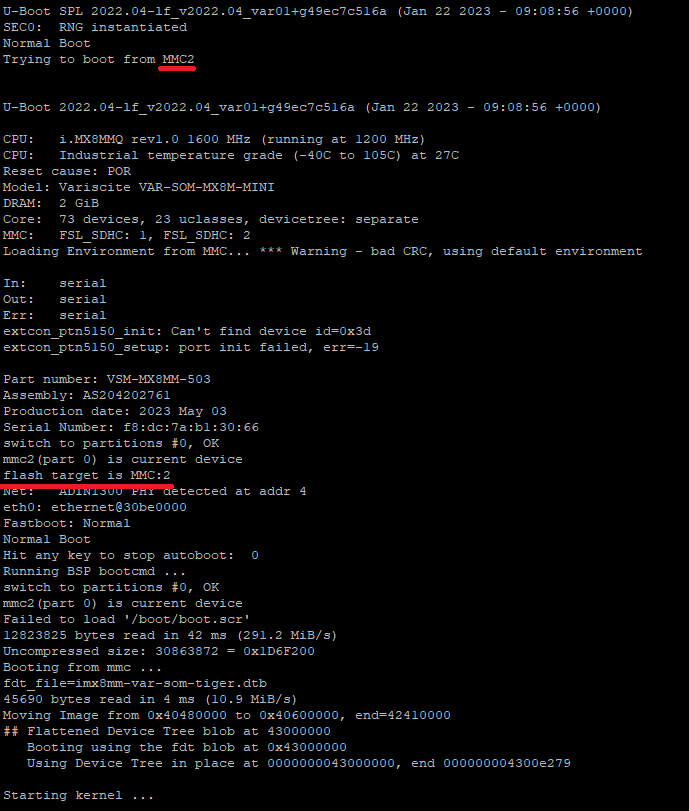
eMMC
DIP switches positions
To boot from the eMMC the DIP switch No. 1 needs to be in the position shown in the picture below.

Power supply
Connect a power supply to the pins shown in the picture below. The suggested power supply is a DC voltage in the range of 12-24 V.
First boot
The connected power supply should initiate the first boot.
Console
Booting logs are displayed in the console, indicating a proper boot from the eMMC, as shown in the picture below.
SD card
DIP switches positions
To boot from the SD card the DIP switch No. 1 needs to be in the position shown in the picture below.

Power supply
Connect a power supply to the pins shown in the picture below. The suggested power supply is a DC voltage in the range of 12-24 V.
First boot
The connected power supply should initiate the first boot.
Console
Booting logs are displayed in the console.
Booting after the power-off command
If the device is turned off by inputting the power-off command in the terminal, the previous boot methods have to be initiated via the reset button placed on the front panel. Its placement is shown in the picture below.

System Console
Tiger City IMX Industrial Computer with Linux OS
UART console
Connecting the adapter to the device
To display the console via UART an RS232 → USB adapter needs to be connected to the pins of the connector shown on the picture below.
Configuring COM port
A serial port terminal needs to be configured with following configuration:
|
Bits per second |
115200 |
| Data bits | 8 |
| Parity | None |
| Stop bits | 1 |
Then, booting from the chosen source should be realized according to the instruction.
SSH console
Finding an IP of the device
The device's IP can be obtained via 2 methods:
- connecting to the UART console and inputting the “ip a” command when logged as root or other user
- using the joystick shown in the picture below the IP can be displayed on the front panel display
Configuring COM port
The SSH terminal needs to be configured with the IP of the device. Then, booting from the chosen source should be realized according to the instruction.
User Management
Tiger City IMX Industrial Computer with Linux OS
Default user
The default user in Tiger is the only one available after the first boot.
- login: root
- no password
Create new users
In order to list all existing users in the system use the following command:
awk -F':' '{print $1}' /etc/passwdTo add a new user and create a home directory for it use the following command:
sudo useradd -m user_nameTo verify that the user was created and view the user’s details use:
sudo id user_nameTo set a new password for the user use the following command:
sudo passwd user_nameAfter that, logging in as a new user will be possible. The current user can be checked with the "whoami" command.
Delete users
A user and its home directory can be deleted with the following command:
sudo userdel -r user_nameUpdating
Tiger City IMX Industrial Computer with Linux OS
System Image
A system image (.swu file) is required for the update. The image is protected by the image checksum and by the image signature. That means a modified image will not be accepted by the device. Only images from our source allow for updates. It is possible to transition from older images to newer ones and vice-versa.
There are several ways to update Tiger:
- through the Tiger console using a file on internal or external storage (eMMC or USB drive),
- through the Tiger console using a file from an external server (FTP or HTTPS),
- via the built-in update server.
The first two options require access to the console (username and password). The third option does not require a password for the device.
Storage (eMMC or USB drive)
- Login to the device console
- Insert external storage or copy the file to Tiger's storage.
- In the console, type
swupdate -i <filename.swu> -k /etc/default/rsakey.pub. - The update will proceed automatically.
External Server (FTP or HTTPS)
- Login to the device console
- For an FTP server, type
swupdate -d -u ftp://<target_ip/file.swu> -a <user>:<password>. - For an HTTPS server, type
swupdate -d -u https://<target_ip/file.swu> -k /etc/default/rsakey.pub. - The update will proceed automatically.
Built-in Update Server
- Connect the device to the network.
- Launch a browser on a PC.
- In the browser, enter
http://<target_ip>:8080. - Select the
.swufile from the PC storage and confirm the selection. - The update will proceed automatically.
Warning! Update files are the default version of firmware. All updates factory reset the device. Make sure you backup all of your important files.
System Overview
Tiger City IMX Industrial Computer with Linux OS
Distribution
Custom Linux distribution based on the Yocto Project. Type uname -a to check installed version, kernel, etc.
Supported languages
- English (US)
- English (GB)
User utilities
Text editor
The default available built-in text editor on the device is vim.
Wi-Fi
The device is equipped with a Wi-Fi module and a NetworkManager library, which allows it to connect to nearby wireless networks.
How to enable and connect with WLAN:
- Check the library status:
systemctl status NetworkManager - If NetworkManager is disabled, type
systemctl start NetworkManager - It is possible to enable it always with autostart:
systemctl enable NetworkManager - Search available networks:
nmcli dev wifi list - Connect with your chosen network:
nmcli dev wifi connect <name> password <password> - Check your connection status with
nmcli connection show --activeorifconfig
System libraries
List of some commonly used available packages:
- Network Manager
- Modem Manager
- Chromium
- Gawk
- OpenCL
- Bzip2
- C++
- Python 3
- SQLite3
- OpenSSL
- Perl 5
- Curl
- Git
- Debuginfo
- glib
- i2c-tools
- GPIO mockup
- gthread
- iperf
- microhttpd
- rpmbuild
- SSL
- swupdate
- Wayland
- Weston
- XCB
- rpm-plugins
- sudo
- xtables
And much more. All the preinstalled system libraries can be found in /usr/lib directory.
User can install any other necessary libraries.
Drivers
System drivers can be displayed using lsmod command.
Restoring Factory Settings
Tiger City IMX Industrial Computer with Linux OS
To factory reset the device, you need to reinstall the current system version or perform an update. The entire process is detailed in the Updating section.
Building Custom System Image
Tiger City IMX Industrial Computer with Linux OS
If you would like to ask a specific question, please visit our Contact Us page for any further information.
Software Examples
How to Use?
Tiger City IMX Industrial Computer with Linux OS
Tiger computer is provided with some basic software examples that can be used as a starting point for developing custom programs.
The examples are available in:
- C
- Python
- Bash
The examples are divided into categories:
C examples
Examples written in C can be built with CMake. Put your source files into one folder and specify its name (${SRC_DIR} dir_name). Then create a CMakeLists.txt file in the parent directory (an example of this file is provided below).
In the parent directory create a new folder named "build" and enter it:
mkdir build && cd buildNext, configure your project using:
cmake ..Then build your project with:
cmake --build .After that, executable files should appear in the same folder.
./file_namePython examples
In order to execute Python files, go to the desired directory and type:
python3 file_name.pyBash examples
In order to execute Bash files, go to the desired directory and type:
bash file_name.shExternal Interfaces
Tiger City IMX Industrial Computer with Linux OS
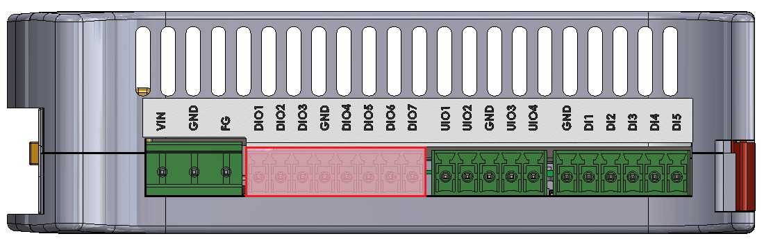
DIO read
This example shows how to use DIO (Digital Input Output) of the Tiger computer in the read mode. After running the program, the state of every DIO will be displayed.
Connections
In order to test, the program uses H1 - H7 pins (diagram provided at the bottom of this page).
DIO write
This example shows how to use DIO (Digital Input Output) of the Tiger computer in the write mode.
Connections
In order to test, the program uses H1 - H7 pins (diagram provided at the bottom of this page).
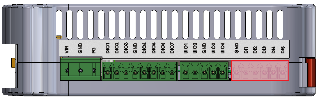
DI read
This example shows how to read the states of the DI (Digital Input) of the Tiger computer. After running the program, the state of every DI will be displayed.
Connections
In order to test, the program uses D1 - D5 pins (diagram provided at the bottom of this page).
ETHERNET
This example shows how to check the Ethernet port connection of the Tiger computer.
Connections
In order to test, the program uses the RJ45 port (diagram provided at the bottom of this page).
1-WIRE
This example shows how to read temperature from the DS18B20+ sensor using the 1-Wire bus of the Tiger computer.
Connections
In order to test, the program uses 1W, 5V and GND pins (diagram provided at the bottom of this page).
RS232
This example shows how to write to and read from the RS232 interface of the Tiger computer.
This example won’t work in the loopback connection test - an external serial monitor is needed.
Connections
In order to test, the program uses T1, R1, T2, R2 and GND pins (diagram provided at the bottom of this page).
RS485
This example shows how to write to and read from the RS485 interface of the Tiger computer.
This example won’t work in the loopback connection test - an external serial monitor is needed.
Connections
In order to test, the program uses A1 - A4, B1 - B4 and GND pins (diagram provided at the bottom of this page).
UIO AI 10 V
This example shows how to use the UIO (Universal Input Output) of the Tiger computer as a voltage AI (Analog Input).
Connections
In order to test, the program uses U1 - U4 pins (diagram provided at the bottom of this page).
UIO AI 20 mA
This example shows how to use the UIO (Universal Input Output) of the Tiger computer as a current AI (Analog Input).
Connections
In order to test, the program uses U1 - U4 pins (diagram provided at the bottom of this page).
UIO AO
This example shows how to use the UIO (Universal Input Output) of the Tiger computer as an AO (Analog Output).
Connections
In order to test, the program uses U1 - U4 pins (diagram provided at the bottom of this page).
UIO DI
This example shows how to use the UIO (Universal Input Output) of the Tiger computer as a DI (Digital Input).
Connections
In order to test, the program uses U1 - U4 pins (diagram provided at the bottom of this page).
USB
This example shows how to open, write to, and read from a USB device plugged into the Tiger computer.
Connections
In order to test, the program uses the USB port (diagram provided at the bottom of this page).
Wi-Fi
This example shows how to connect the Tiger computer to a Wi-Fi access point.
Ports diagram
Internal Devices
Tiger City IMX Industrial Computer with Linux OS
Buzzer
This example shows how to use the integrated buzzer of the Tiger computer. The buzzer will generate a sound for a few seconds and then turn itself off.
EEPROM erase
This example shows how to erase the EEPROM memory of the Tiger computer.
EEPROM read
This example shows how to read from the EEPROM memory of the Tiger computer.
EEPROM SN read
This example shows how to read from the EEPROM SN (read-only) memory of the Tiger computer.
EEPROM write
This example shows how to write some sample string to the EEPROM memory of the Tiger computer.
FLASH erase
This example shows how to erase the FLASH memory of the Tiger computer.
FLASH read
This example shows how to read from the FLASH memory of the Tiger computer.
FLASH write
This example shows how to write some sample string to the FLASH memory of the Tiger computer.
GSM reset
This example shows how to reset the GSM module of the Tiger computer.
RTC
This example shows how to read date and time from the RTC (Real Time Clock) of the Tiger computer.
Watchdog
This example shows how to view the watchdog service status of the Tiger computer.
Front Panel
Tiger City IMX Industrial Computer with Linux OS
DIP read
This example shows how to read the states of the DIP switches of the Tiger computer’s front panel. After running the program, the state of every DIP switch will be displayed.
Joystick
This example shows how to get inputs from the joystick located on the front panel of the Tiger computer.
LED
This example shows how to change the colors of the RGB LEDs located on the front panel of the Tiger computer.
OLED
This example shows how to use the OLED screen located on the front panel of the Tiger computer.
TCXV example web-app
Tiger City IMX Industrial Computer with Linux OS
The device hosts a web application that can be accessed by connecting to it via a local network.
Type node /opt/redisage/example-app/server.js in the device's terminal to start hosting an example web application.
Example web application
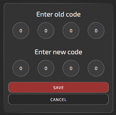
Login
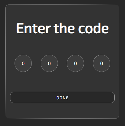
The default code is 0000. After logging in, a user can change it. The code settings are in the upper-right corner of the site, next to the help button.
Panels
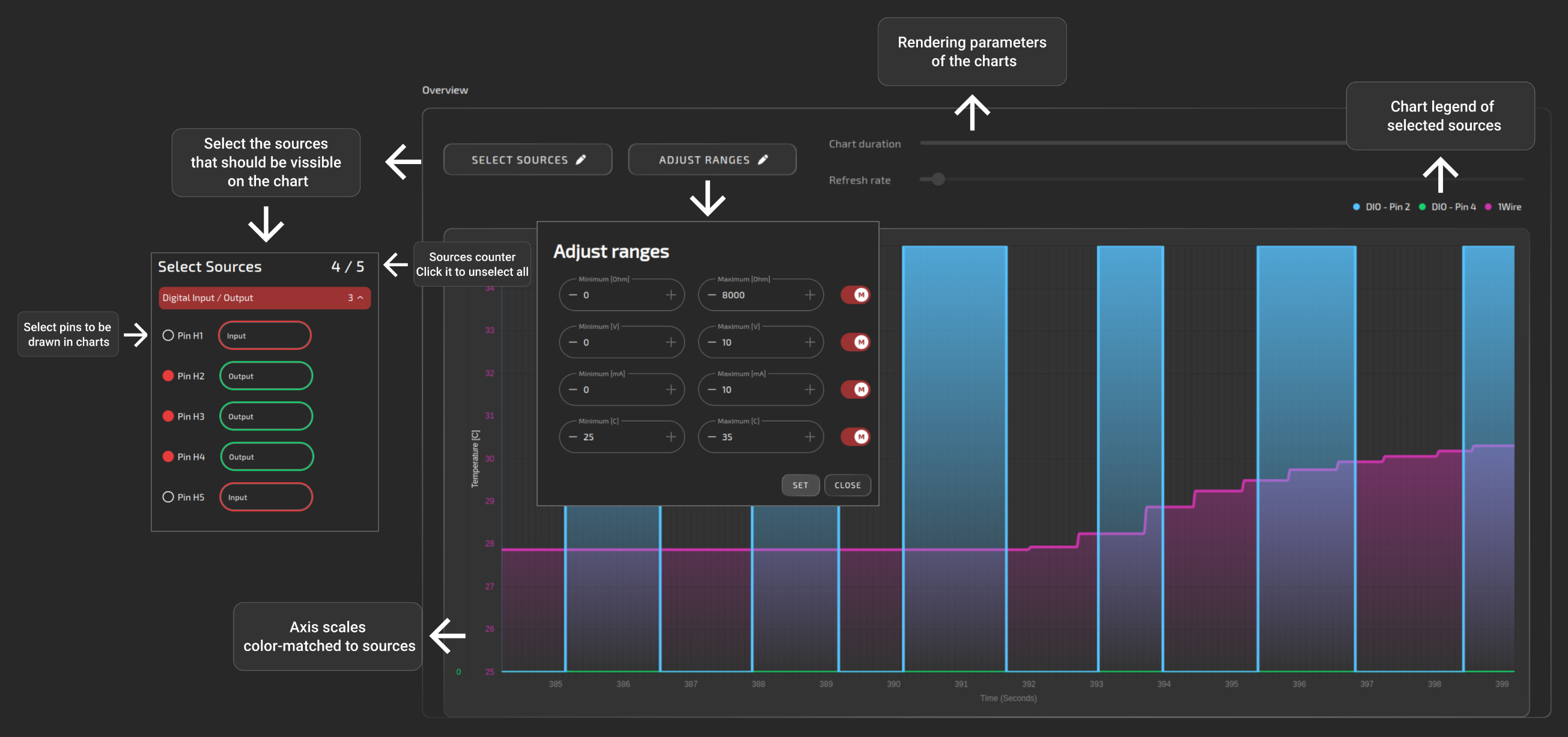
Overview
The purpose of this panel is only to display data from different interfaces on a common chart. Output pins are to be controlled via individual interfaces pages.
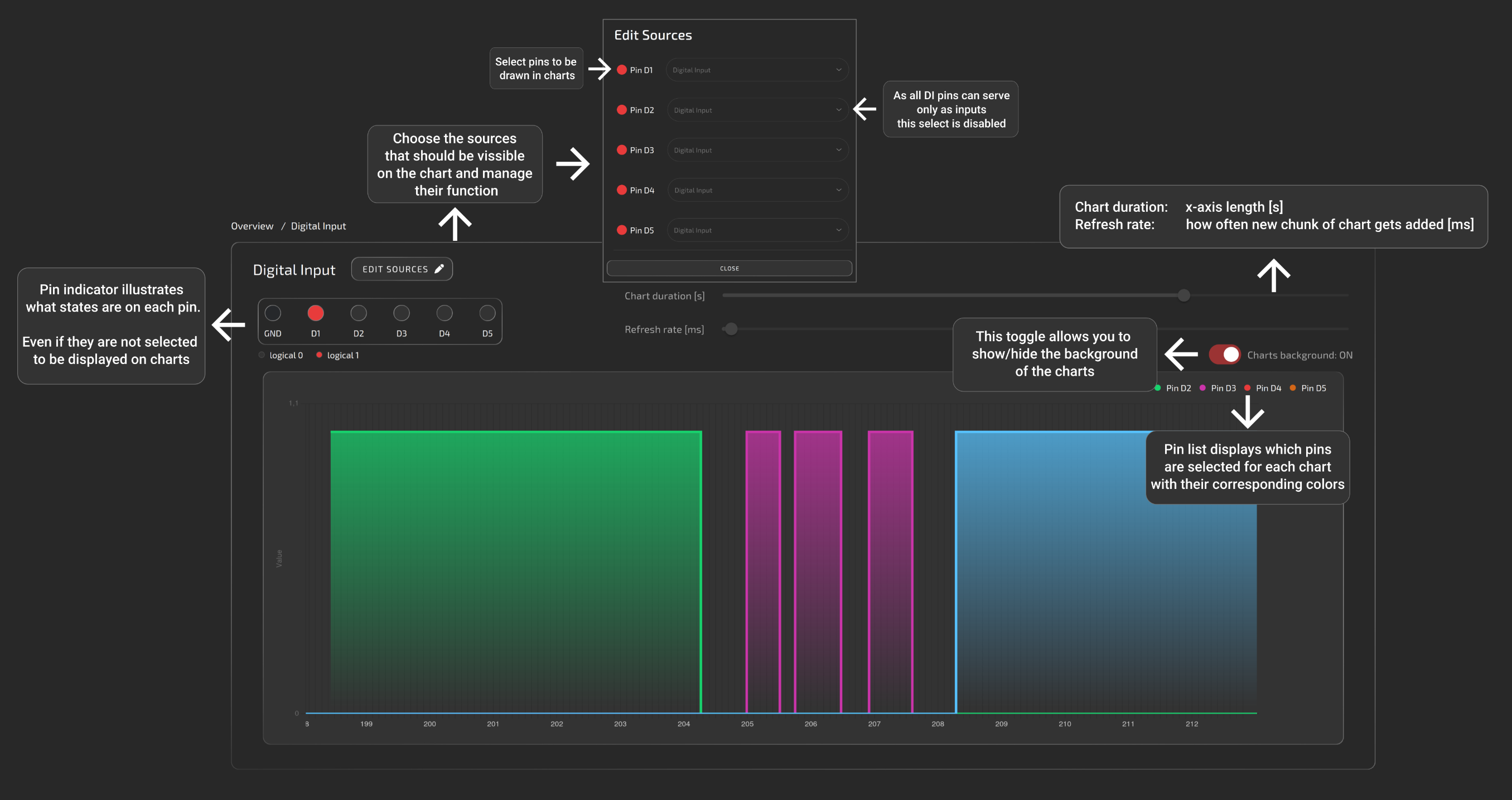
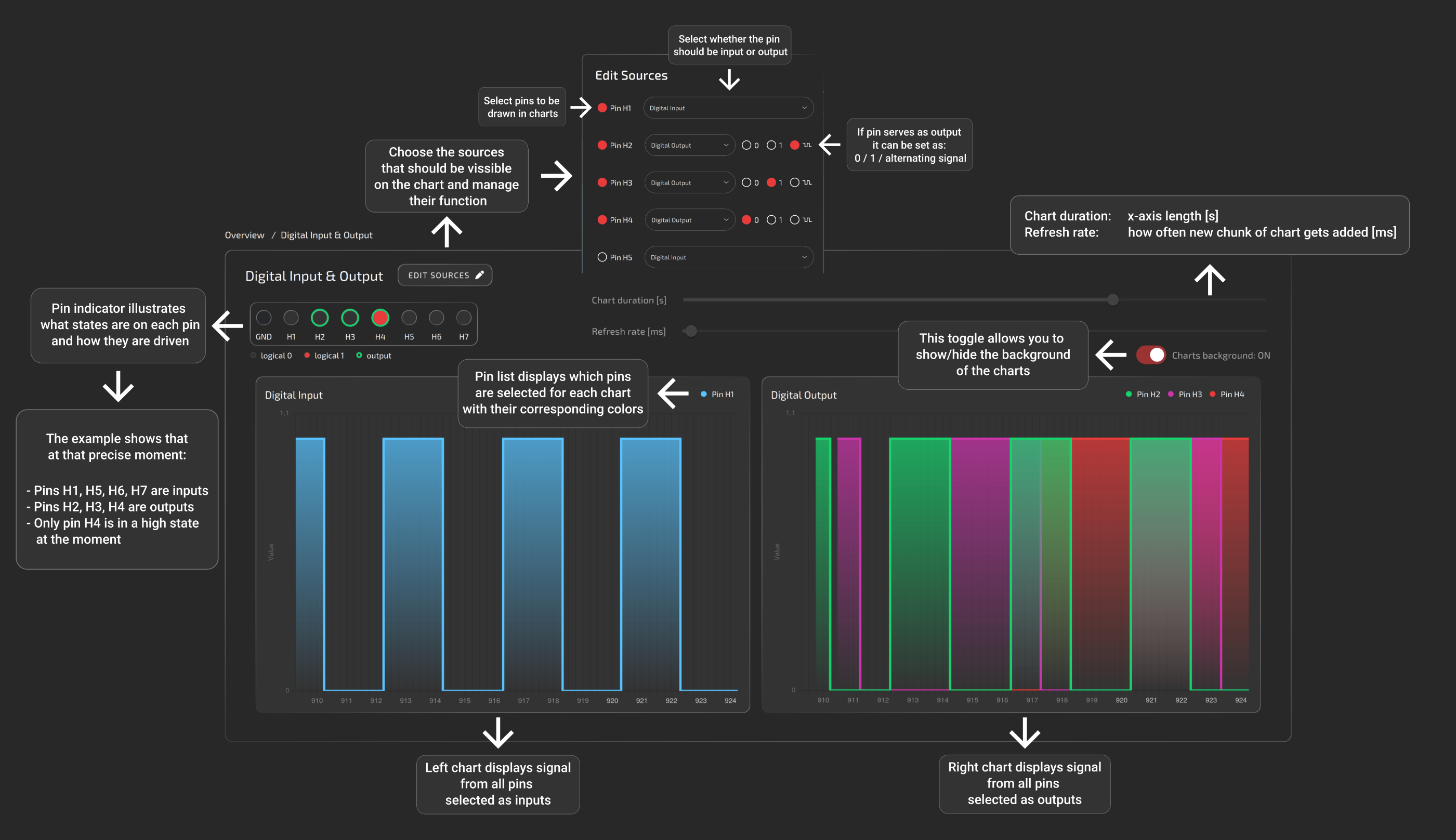
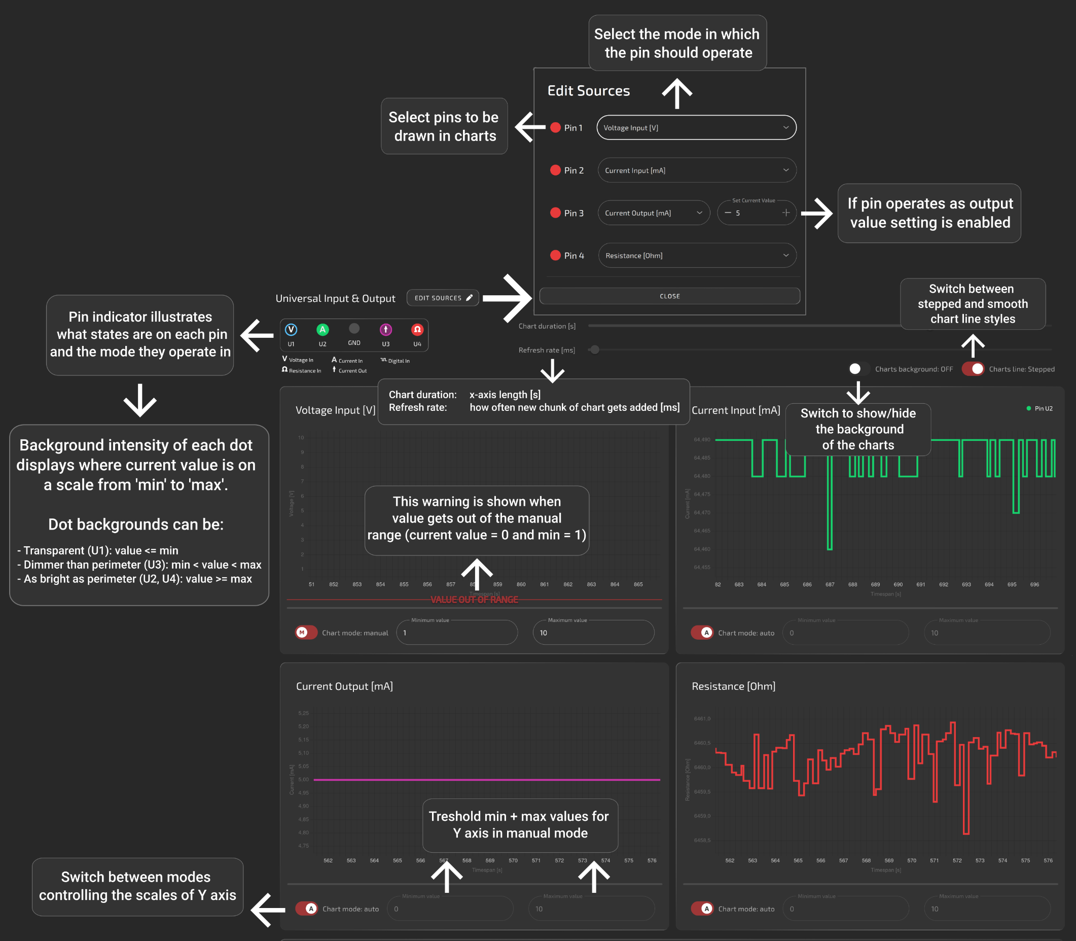
All of the below help images are also available on the site by clicking the question mark in the upper-right corner.
Digital input
Digital input/output
Universal input/output
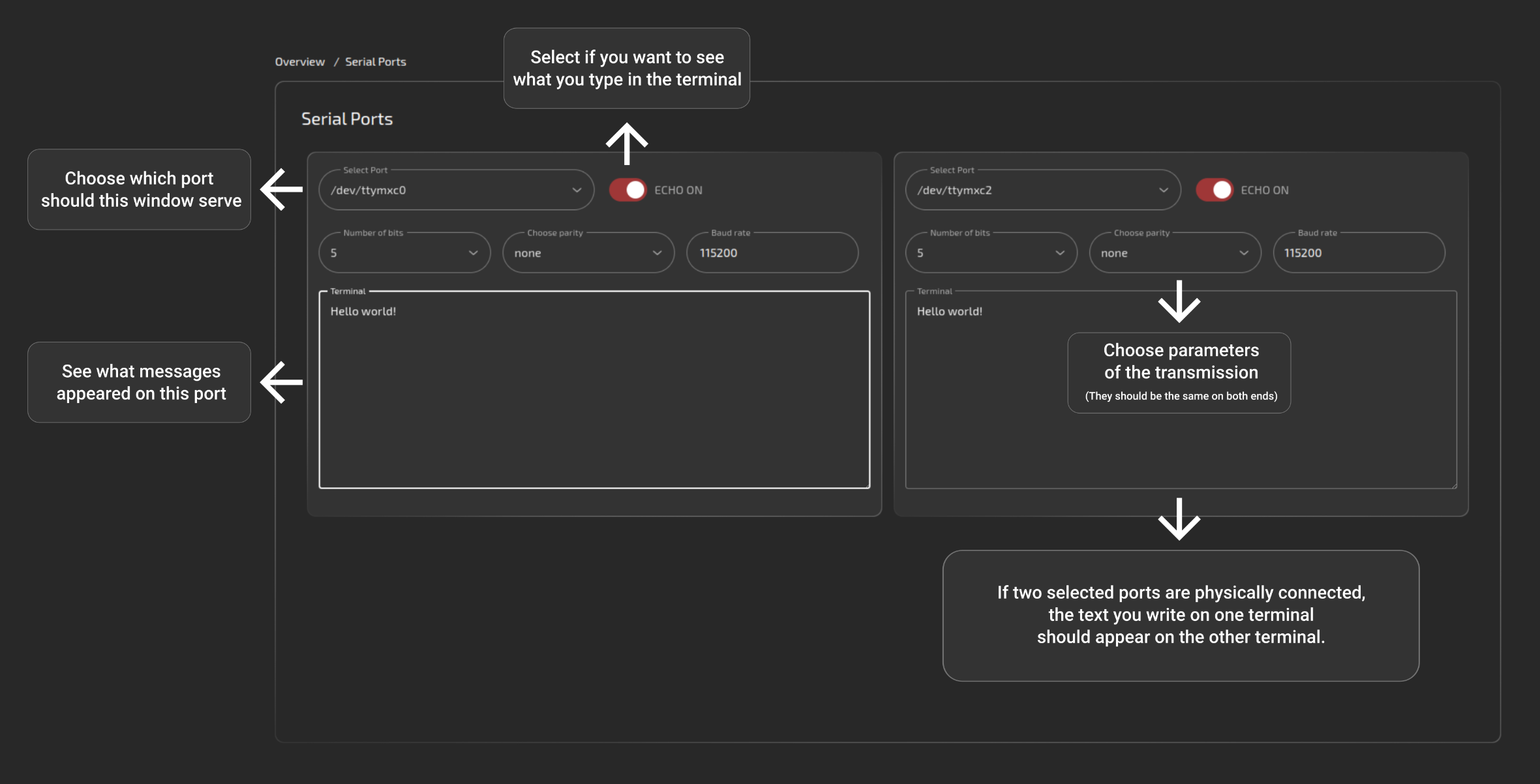
Serial
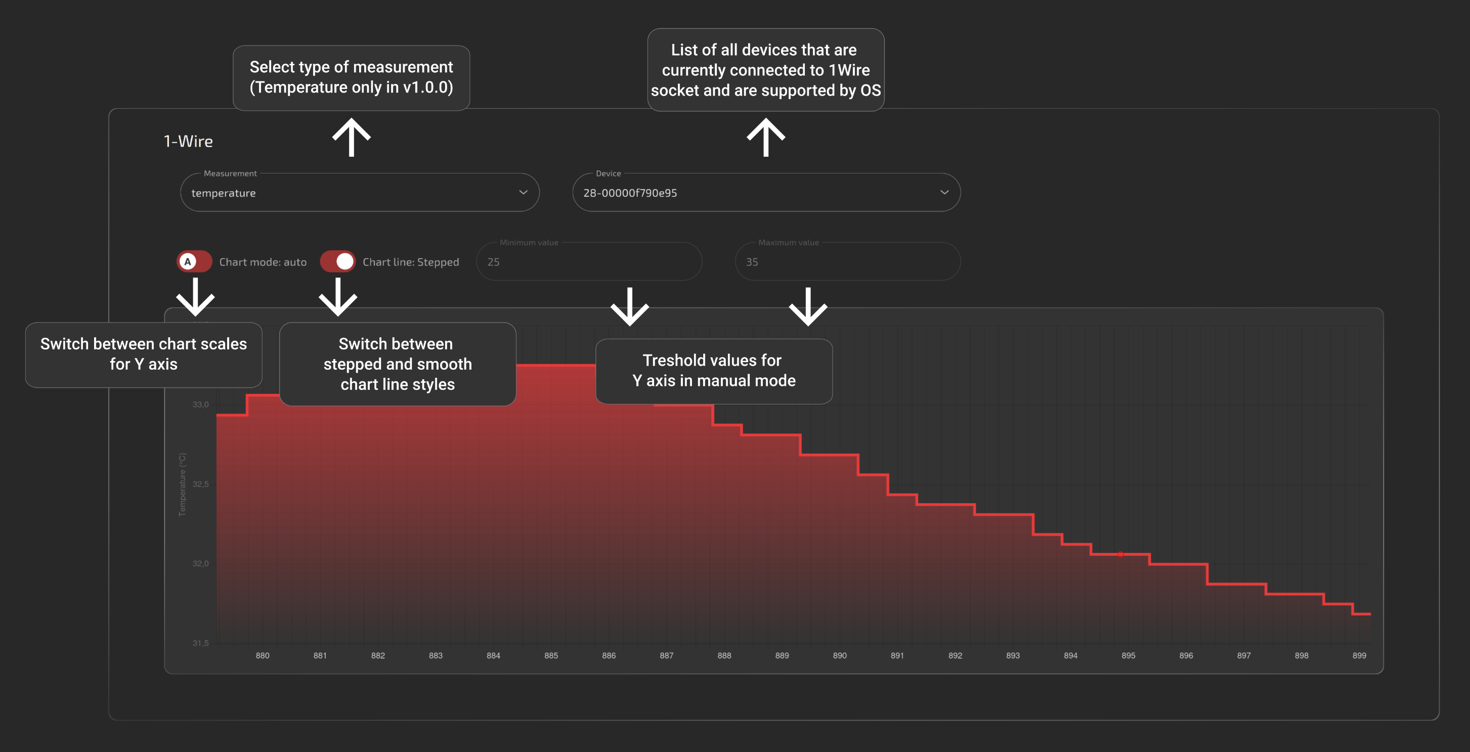
1-Wire
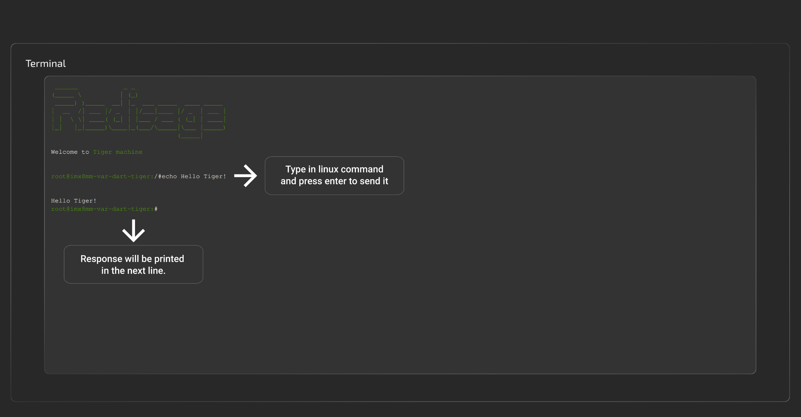
Terminal
This panel serves as a terminal emulator for basic communication with the device. It allows navigating through the directories, looking up logs or connected devices and much more.
GitHub repository: soon.
Contact Us
- Main web page
- E-mail:
online@redisage.com - Phone number:
+48 71 70 00 140 - Address:
NSG 4L Sp. z o.o.
ul. Trzy Lipy 3B
80-172 Gdańsk
(POLSKA) - More information
Common Resources
Internal Communication Lines
The device is equipped with multiple internal communication lines of the following types:
SPI
The device is equipped with the following SPI communication lines.
SPI1
|
Signal |
Processor pin |
Default function |
|
Chip select 0 |
AD18 |
SPI1_CS0 |
|
Chip select 1 |
AG23 |
SPI1_CS1 |
|
Master in slave out |
A7 |
SPI1_MISO |
|
Clock |
D6 |
SPI1_SCLK |
|
Master out slave in |
B7 |
SPI1_MOSI |
SPI2
|
Signal |
Processor pin |
Default function |
|
Chip select 0 |
A6 |
SPI2_CS0 |
|
Chip select 1 |
AF12 |
SPI2_CS1 |
|
Chip select 2 |
AB19 |
SPI2_CS2 |
|
Master in slave out |
A8 |
SPI2_MISO |
|
Clock |
E6 |
SPI2_SCLK |
|
Master out slave in |
B8 |
SPI2_MOSI |
I2C
The device is equipped with the following I2C communication lines.
I2C2
Device name: /dev/i2c-1
|
Signal |
Processor pin |
Default function |
|
Clock |
D10 |
I2C2_SCL |
|
Data |
D9 |
I2C2_SDA |
I2C3
Device name: /dev/i2c-2
|
Signal |
Processor pin |
Default function |
|
Clock |
E10 |
I2C3_SCL |
|
Data |
F10 |
I2C3_SDA |
I2C4
Device name: /dev/i2c-3
|
Signal |
Processor pin |
Default function |
|
Clock |
D13 |
I2C4_SCL |
|
Data |
E13 |
I2C4_SDA |
UART
The device is equipped with the following UART communication lines.
UART1
Device name: /dev/ttymxc0
|
Signal |
Processor pin |
Default function |
|
Receive (UART1 RX) |
E14 |
UART1_RXD |
|
Transmit (UART1 TX) |
F13 |
UART1_TXD |
UART2
Device name: /dev/ttymxc1
|
Signal |
Processor pin |
Default function |
|
Receive (UART2 RX) |
X |
UART2_RXD |
|
Transmit (UART2 TX) |
X |
UART2_TXD |
UART3
Device name: /dev/ttymxc2
|
Signal |
Processor pin |
Default function |
|
Receive (UART3 RX) |
E18 |
UART3_RXD |
|
Transmit (UART3 TX) |
D18 |
UART3_TXD |
UART4
Device name: /dev/ttymxc3
|
Signal |
Processor pin |
Default function |
|
Receive (UART4 RX) |
F19 |
UART4_RXD |
|
Transmit (UART4 TX) |
F18 |
UART4_TXD |
Introduction
Tiger City IMX Industrial Computer with Linux OS
The Tiger City IMX minicomputer uses Linux operating systems and is equipped with several communication interfaces such as: Ethernet, USB 2.0, HDMI, GSM, RS232, RS485, 1-Wire and multiple analog-digital inputs and outputs. It can also be configured to include a Wi-Fi module and encryption modules that increase the security of the device. The casing enables installation on the DIN rail. The front panel has switches, an OLED display and a joystick for manual control of the device operation.
Drawings
Placement of peripherals
Power supply
Detailed connections diagram
Enclosure