Internal Devices
{{@273#bkmrk-tiger-city-imx-embed}}
- {{@166#bkmrk-internal-expansion-c}}
- {{@166#bkmrk-watchdog-%2B-reset}}
- {{@166#bkmrk-eeprom%E2%80%8E%E2%80%8E}}
- {{@166#bkmrk-flash}}
- {{@166#bkmrk-rtc}}
- {{@166#bkmrk-esp32-microcontrolle}}
- {{@166#bkmrk-tpm-2.0}}
- {{@166#bkmrk-secure-element-to136}}
- {{@166#bkmrk-buzzer}}
Internal expansion connectorsconnector
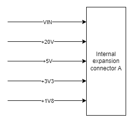
Internal Expansion Connector A
Part number: FH1243-208CWG0MUT01
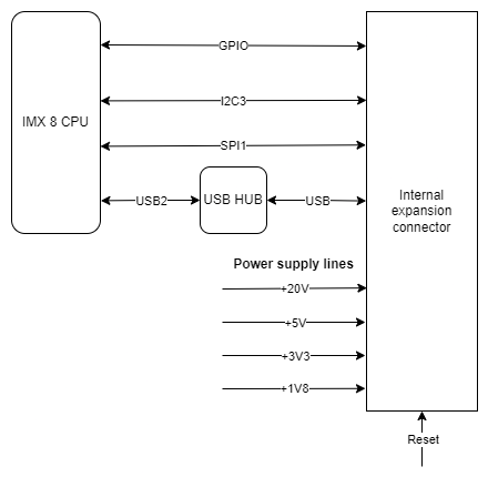
Internal expansion connector connections diagram
Internal expansion connector connections table
|
|
|
|
|
|
|
|
|
|
|
|
|
|
|
|
|
|
|
|
|
|
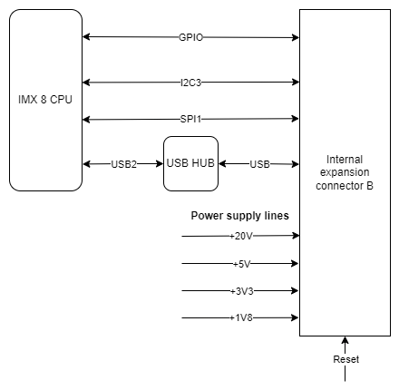
Internal Expansion Connector B
Part number: FH1234-221CWG0MUT01
Internal expansion connector connections diagram
Internal expansion connector connections table
|
Connector pin |
Description |
|
1 |
GND |
|
2 |
VIN |
|
3 |
GND |
|
4 |
SPI1 MOSI |
|
5 |
GND |
|
6 |
SPI1 SCLK |
|
7 |
GND |
|
8 |
SPI1 MISO |
|
9 |
GND |
|
10 |
RTC battery power supply |
|
11 |
External watchdog reset |
|
12 |
NC |
|
13 |
GND |
|
14 |
NC |
|
15 |
NC |
|
16 |
NC |
|
17 |
GPIO4 IO25 |
|
18 |
GND |
|
19 |
GPIO1 IO07 |
|
20 |
GPIO4 IO21 |
|
21 |
GPIO5 IO09 |
|
22 |
Global reset |
|
23 |
GND |
|
24 |
I2C3 SDA |
|
25 |
I2C3 SCL |
|
26 |
GND |
|
27 |
+3V3 |
|
28 |
GND |
|
29 |
USB3 positive pole |
|
30 |
USB3 negative pole |
|
31 |
GND |
|
32 |
+20V |
|
33 |
UIO reset |
|
34 |
NC |
|
35 |
NC |
|
36 |
+1V8 |
|
37 |
+1V8 |
|
38 |
GND |
|
39 |
+5V |
|
40 |
+5V |
|
41 |
GND |
|
42 |
GND |
|
43 |
VIN |
|
44 |
GND |
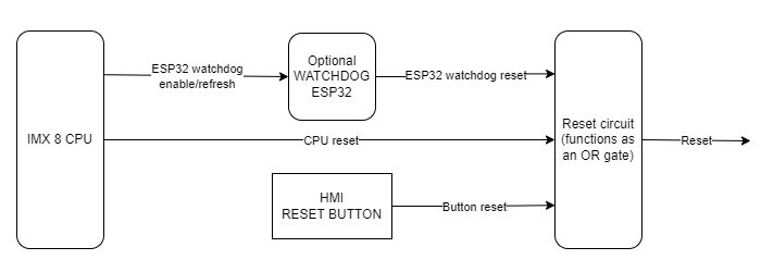
Watchdog + reset
The device is equipped with a watchdog and a reset circuit.
Watchdog and Reset circuit connections diagram
CPU connections table
|
Signal |
CPU pin |
Default function |
User-space name |
|
ESP32_WDT_EN |
AF13 |
GPIO1_IO03 |
gpiochip0 3 |
|
ESP32_WDI |
AF14 |
GPIO1_IO01 |
gpiochip0 1 |
|
SOM_GLOB_NRST |
AD6 |
GPIO5_IO02 |
gpiochip4 2 |
ESP32 reset
The device is equipped with an ESP32 microcontroller, which can optionally serve as a watchdog.
EEPROM
The device is equipped with 2 EEPROM memory modules. EEPROM B is reserved for the producer's purposes and it is read-only.
EEPROM device
Part number: M24C02-RMC6
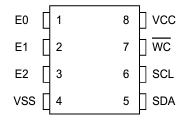
EEPROM A connections table
|
EEPROM pin |
Description |
User-space name |
|
1 |
Address pin 0 (GND) |
X |
|
2 |
Address pin 1 (+3V3) |
X |
|
3 |
Address pin 2 (+3V3) |
X |
|
5 |
I2C2 data |
X |
|
6 |
I2C2 clock |
X |
|
7 |
EEPROM write-protect |
gpiochip0 2 |
EEPROM B (EEPROM SN) connections table
|
EEPROM pin |
Description |
User-space name |
|
1 |
Address pin 0 (GND) |
X |
|
2 |
Address pin 1 (+3V3) |
X |
|
3 |
Address pin 2 (GND) |
X |
|
5 |
I2C2 data |
X |
|
6 |
I2C2 clock |
X |
|
7 |
EEPROM write-protect (pull-up) |
X |
EEPROM connection diagram
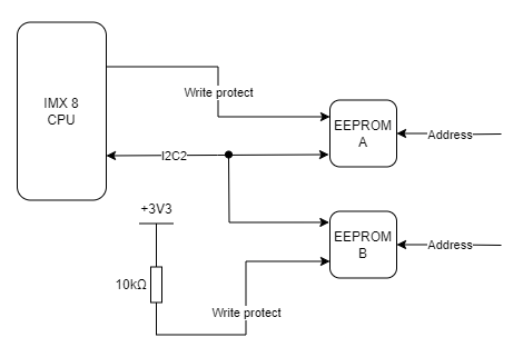
User-space access
EEPROM A device name: /sys/bus/nvmem/devices/2-00523
EEPROM B device name: /sys/bus/nvmem/devices/2-00561
{{@134#bkmrk-i2c3}}
EEPROMs A and B are connected to the CPU with the I2C2 interface.
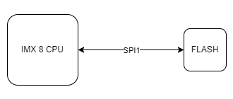
FLASH
Part number: W25Q64JVSSIQ
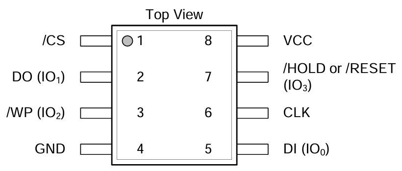
FLASH connections table
|
FLASH pin |
Description |
User-space name |
|
1 |
SPI1_CS0 |
X |
|
2 |
SPI1_MISO |
X |
|
3 |
SPI1_WP |
X |
|
5 |
SPI1_MOSI |
X |
|
6 |
SPI1_SCLK |
X |
|
7 |
SPI1_HOLD |
X |
FLASH connection diagram
User-space access
FLASH device name: /dev/mtdblock0
{{@134#bkmrk-spi1}}
FLASH is connected to the CPU with the SPI1 interface.
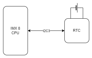
RTC
The device is equipped with a real-time clock operating at 32.768 kHz with a tolerance of 20 ppm. The RTC clock is connected to a DR2032 battery which is its power supply.
RTC device
Part number: DS1338
RTC connection diagram
User-space access
Device name: /sys/class/rtc/rtc0
RTC connections table
|
RTC pin |
Description |
|
1 |
Clock oscillator pin no. 1 |
|
2 |
Clock oscillator pin no. 2 |
|
3 |
Battery power pin |
|
5 |
I2C3 data |
|
6 |
I2C3 clock |
{{@134#bkmrk-i2c4}}
The real-time clock is connected to the CPU with the I2C3 interface.
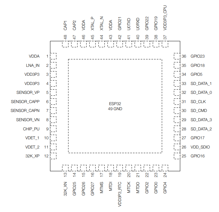
ESP32 microcontroller
The device is equipped with an internal ESP32 microcontroller used for internal purposes.
ESP32 device
Part number: ESP32-DOWD
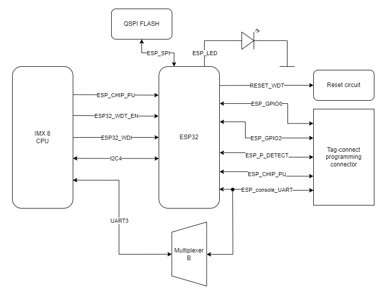
ESP32 connections table
|
ESP32 pin |
Description |
|
8 |
ESP_P_DETECT |
|
9 |
ESP_CHIP_PU |
|
14 |
ESP32_WDT_EN |
|
15 |
ESP32_WDI |
|
22 |
ESP_GPIO2 |
|
23 |
ESP_GPIO0 |
|
24 |
RESET_WDT |
|
25 |
LED_ESP |
|
26 |
VDD_SDIO |
|
28 |
ESP_SPI_HD |
|
29 |
ESP_SPI_WP |
|
30 |
ESP_SPI_CS0 |
|
31 |
ESP_SPI_CLK |
|
32 |
ESP_SPI_O |
|
33 |
ESP_SPI_D |
|
38 |
I2C4_SCL |
|
39 |
I2C4_SDA |
|
40 |
ESP_CONSOLE_RX |
|
41 |
ESP_CONSOLE_TX |
ESP32 connections diagram
CPU connections table
|
Signal |
CPU pin |
Default function |
User-space name |
|
ESP_GPIO_0 |
AC14 | GPIO3_IO22 | gpiochip2 22 |
| ESP_GPIO_2 | AC15 | GPIO3_IO20 | gpiochip2 20 |
|
ESP32_WDI |
AF14 | GPIO1_IO01 | gpiochip0 1 |
|
ESP32_WDT_EN |
AF13 |
GPIO1_IO03 |
gpiochip0 3 |
{{@134#bkmrk-i2c4-1}}
The microcontroller is connected to the CPU via the I2C4 interface.
{{@134#bkmrk-uart3-1}}
The microcontroller is connected to the CPU via the UART3 interface.
TPM 2.0
The device is equipped with a trusted platform module in 2.0 standard.
TPM device
Part number: SLM9670
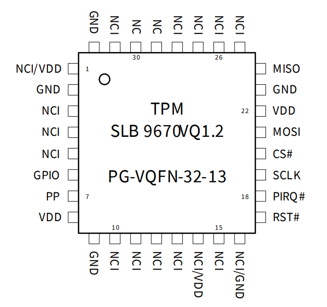
TPM connections table
|
TPM pin |
Description |
|
17 |
Reset |
|
18 |
TPM_IRQ |
|
19 |
SPI2 clock |
|
20 |
SPI2 chip select |
|
21 |
SPI2 master out slave in |
|
24 |
SPI2 master in slave out |
User-space access
Device name: /sys/class/tpm
TPM connection diagram
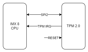
CPU connections table
|
Signal |
CPU pin |
Default function |
User-space name |
|
TPM_IRQ |
AC24 |
GPIO4_IO23 |
gpiochip3 23 |
{{@134#bkmrk-%C2%A0}}
Trusted platform module is connected to the CPU with the SPI2 interface.
Secure element TO136
The device is equipped with a secure element that can be used for encoding data.
Secure element device
Part number: IDEMIA TO136
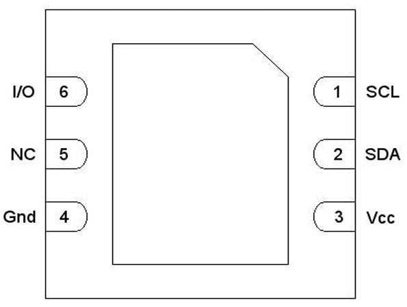
Secure element connections table
|
Secure element pin |
Description |
|
1 |
I2C4 clock |
|
2 |
I2C4 data |
|
3 |
+3V3 |
|
6 |
IDLE/BUSY state report |
User-space access
Device name: (...)
Secure element connections diagram
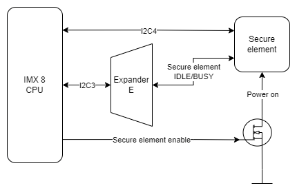
{{@136#bkmrk-expander-e}}
The secure element is connected to the Expander E connected to the CPU via the I2C3 interface.
{{@134#bkmrk-i2c4-1}}
The secure element is connected to the CPU via the I2C4 interface.
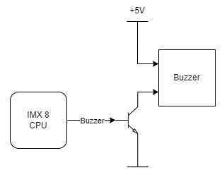
Buzzer
The device is equipped with a buzzer.
Buzzer device
Part number: LD-BZEG-0905
User-space access
Device name: gpiochip3 7
Buzzer connection diagram