Hardware
{{@264#bkmrk-open-iot-and-iiot-ga}}
Features
|
Features |
 |
|---|---|
|
Open IoT gateway |
|
|
ESD protection for the RS485 data line |
|
|
Power supply: +12 to +30 VDC |
|
|
Transmission speed up to 115200 bps |
|
|
Tx, Rx and power LED indicators |
|
|
RS485 embedded termination 120 ohm |
|
|
Operating temperatures: -40°C to +75°C |
|
|
DIN-rail mounting |
|
|
Dimensions: 90x56.4x22.5 mm |
|
|
3 years warranty |
|
|
Customization of OEM is welcomed |
{{@169}}
{{@263#bkmrk-specifications%E2%80%8E%E2%80%8E%E2%80%8E}}
{{@263#bkmrk-redisage-pn-p01-p02-}}
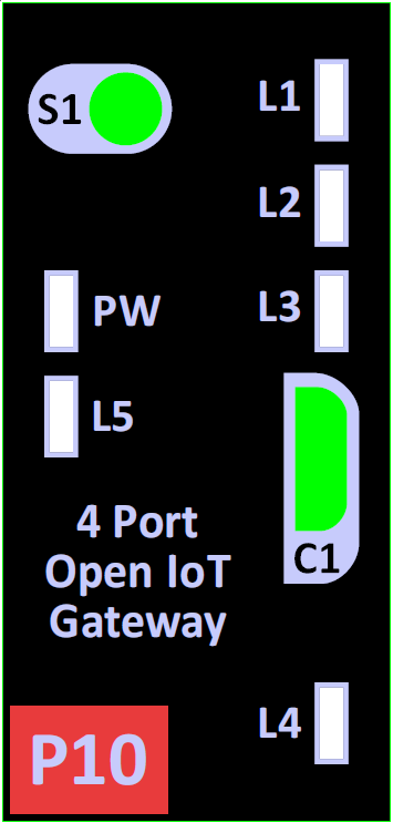
LED indicators
| Gateways P10 - P12 |
||
 |
||
| LED indicator | Color | Function |
| PW | Blue | Power |
| L1 | Green | LED 1 |
| L2 | Green | LED 2 |
| L3 | Yellow | LED 3 |
| L4 | Red | LED 4 |
| L5 | Red | LED 5 |
{{@263#bkmrk-pin-assignments}}
{{@263#bkmrk-p01-%C2%A0-p02-%C2%A0}}
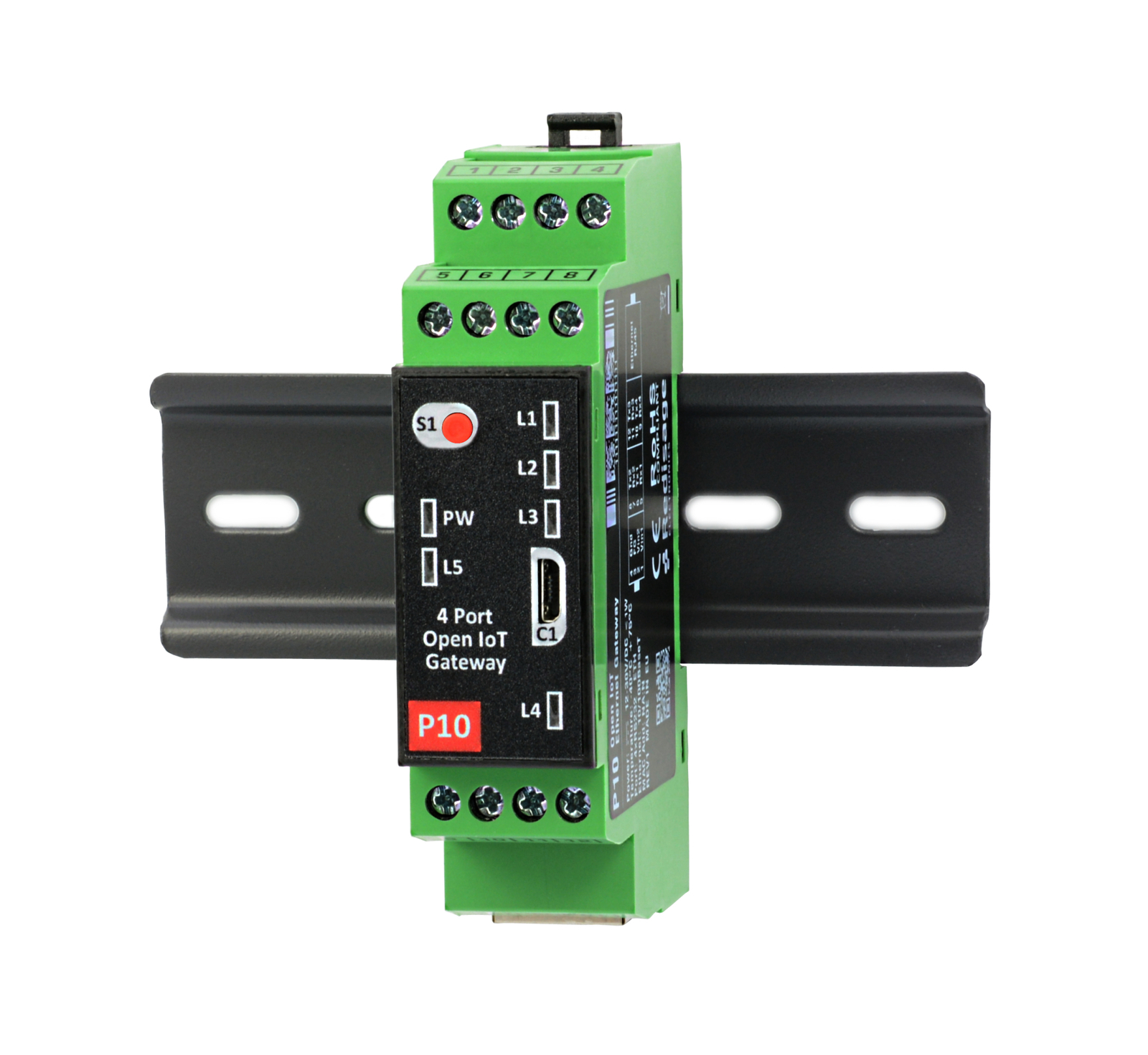
Board overview
The complete Open IoT and IIoT Gateway kit consists of:
- developer module
- power supply module
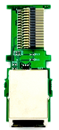
- RJ45 network adapter
- hardware programmer (TagConnect + adapter for ST-LINK)
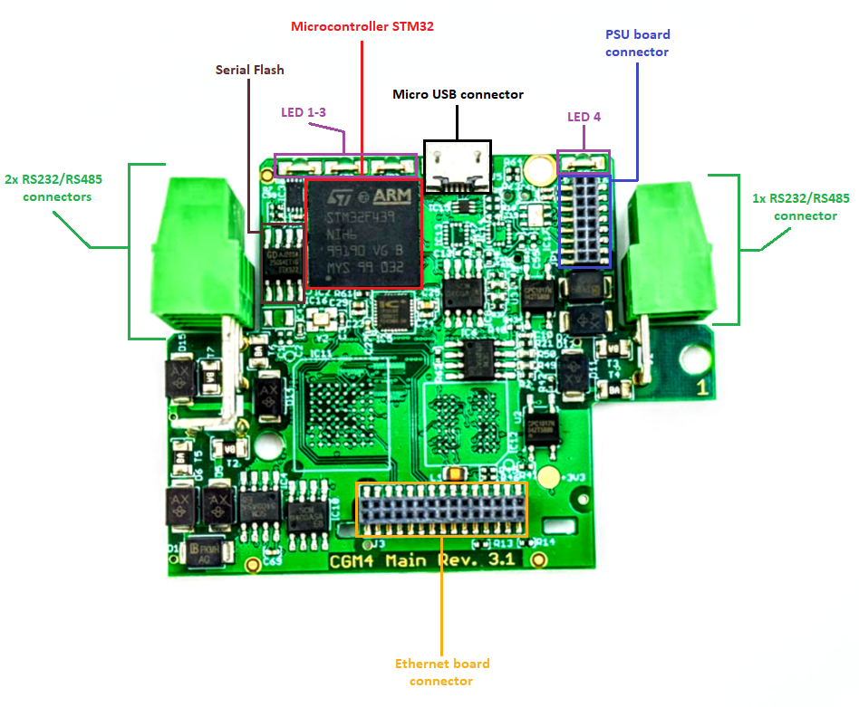
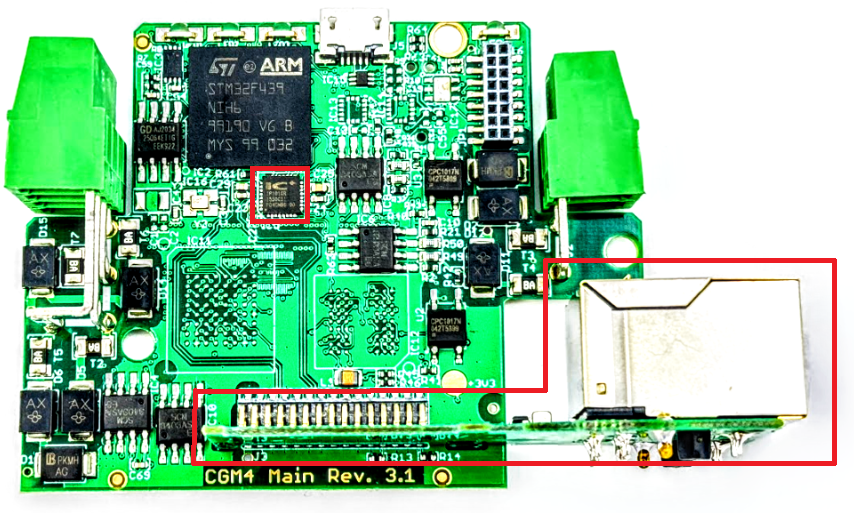
Main Board
Power Supply Board
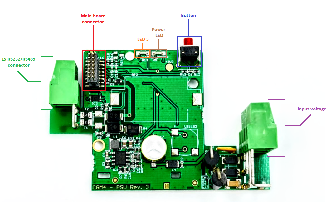
Power input & RS232/RS485 ports
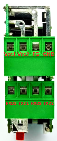
- Vcc1, Vcc2 - power supply input 9-30 VDC
- FG - frame ground
- GND - power supply ground
RS232/RS485 ports depend on the device variant.
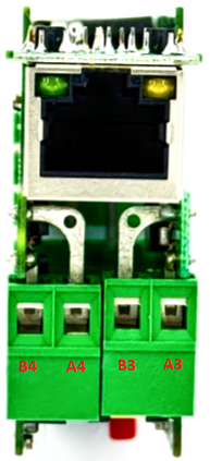
Ethernet
To support the Ethernet network interface communication, the network adapter available in the kit must be installed on the module (pay attention to its correct installation). This interface is supported by the external IP101G physical layer which communicates with the STM32 microcontroller.
Ethernet
Power input pinout