Data Sheet
RemoteCOM is a complete hardware and software solution for creating remote communication ports. The software part can be uploaded to any of the Redisage C20 - C25 Ethernet Converters. It provides a communication between a LAN host and a device equipped with RS232/RS485 serial interfaces. A dedicated app makes it easy and fast to configure and deploy. There is a possibility to create virtual COM ports with the Redisage Configurator to minimize number of cables.
|
C20 C21 C22 C23 C24 C25
|
Features
|
Introduction
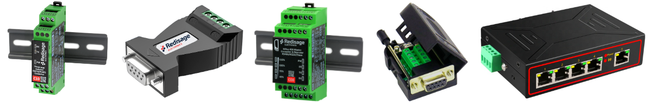
C20 - C22 are a products family of reliable converters based on the ESP32 Xtensa LX6 microcontroller, extending the capabilities of industrial devices.
C23 - C25 are a products family of reliable converters based on the STM32F4 microcontroller, extending the capabilities of industrial devices.
The addition of a network interface allows remote access and full control over a communication via a computer.
The user performs the basic configuration of transmission parameters in a browser or via a Telnet/serial console.
Dedicated EMC integrated circuits guarantee improved connection quality by limiting the impact of the interferences typical for an industrial environment.
{{@170#bkmrk-specifications}}
{{@170#bkmrk-redisage-pn-c20-c21-}}
Variants
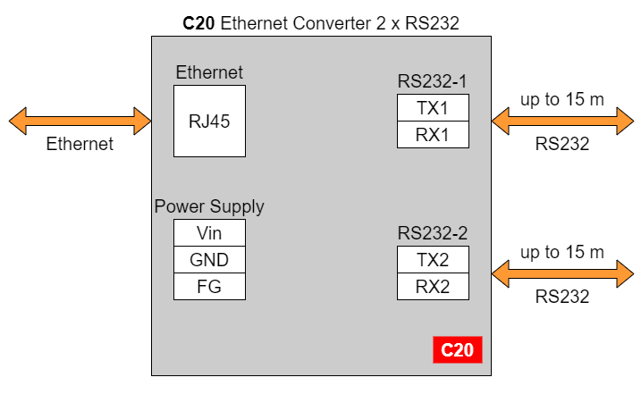
C20 - Ethernet Converter 2 x RS232
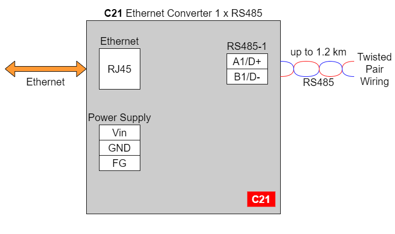
C21 - Ethernet Converter 1 x RS485
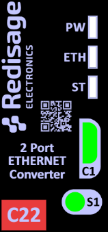
C22- Ethernet Converter 2 x RS232/RS485
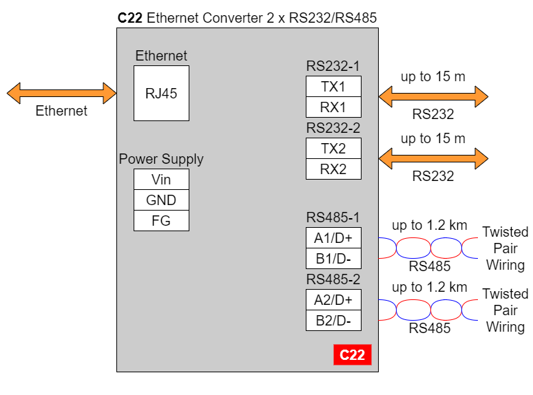
In the C22 converter user should use only RS232 or only RS485 interface of one port as they occupy the same internal bus of the device.
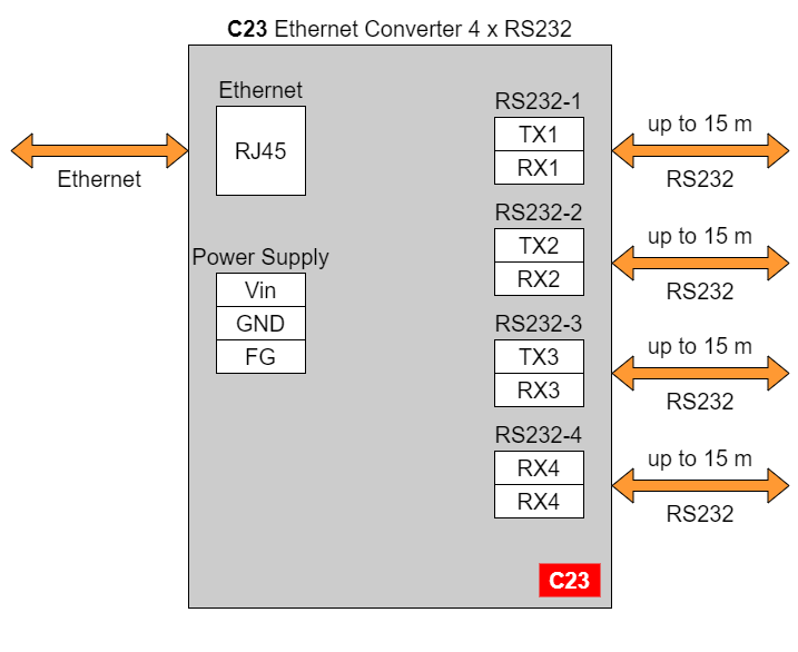
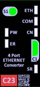
C23 - Ethernet Converter 4 x RS232
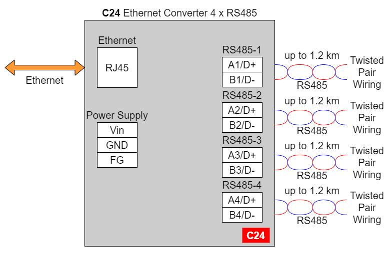
C24 - Ethernet Converter 4 x RS485
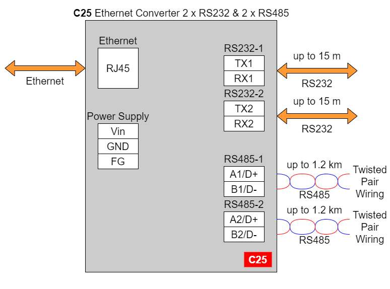
C25 - Ethernet Converter 2 x RS232 & 2 x RS485
{{@169#bkmrk-frame-ground-fg}}
{{@169#bkmrk-electronic-circuits-}}
{{@169#bkmrk-frame-ground-fg-conn}}
{{@169#bkmrk-if-earth-ground-is-n}}
{{@170#bkmrk-pin-assignments}}
{{@170#bkmrk--14}}
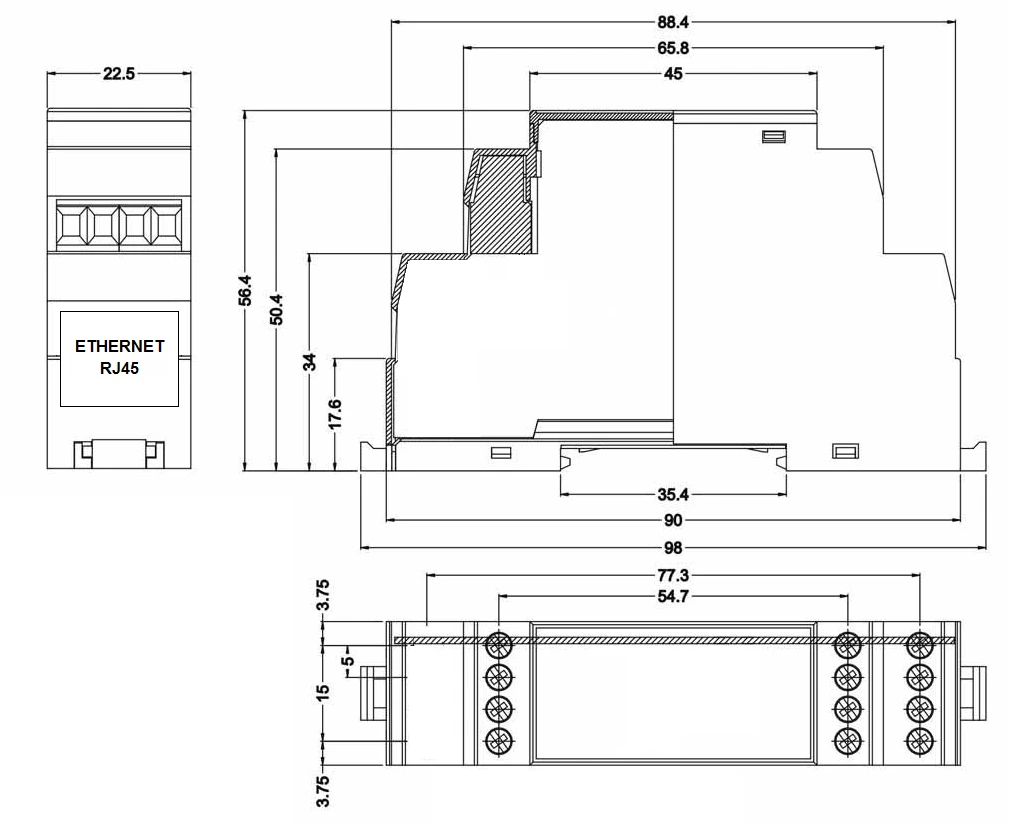
Enclosure dimensions
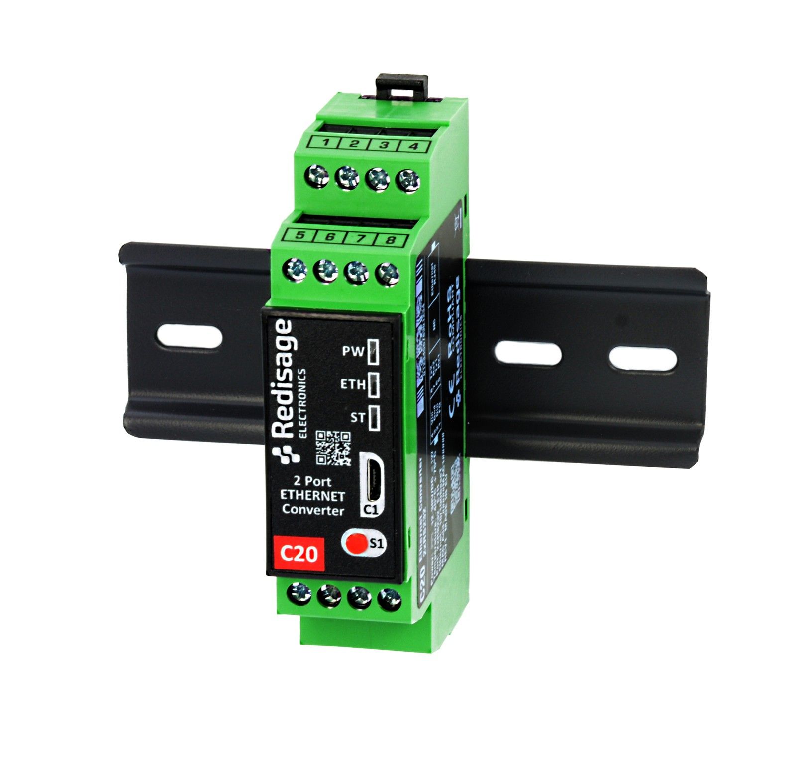
2U Module Enclosure.
98 x 22.5 x 56.4
Units: mm.
Getting started
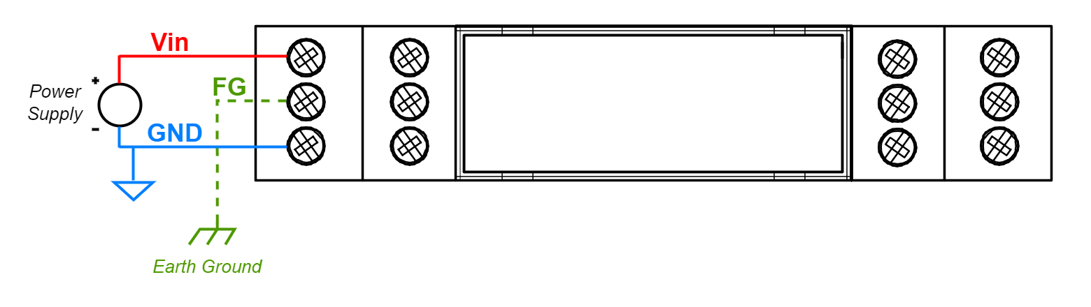
Power supply
Ethernet converters C20 - C25 have wide voltage power input (12-30 VDC) and the power consumption is less than 1 W.
LED indicators
Ethernet converters C20 - C22 have 3 LED indicators:
- PW LED Blue - Power
- ETH LED Green - Network activity
- ST LED Orange - USB-UART serial console mode
Ethernet converters C23 - C25 have 5 LED indicators:
- PW LED Blue - Power
- ER LED Yellow - Error
- ETH LED Green - Network activity
- COM LED Green - RS232/RS485 activity
- CN LED Yellow - Console mode
- SR LED Red - Service mode
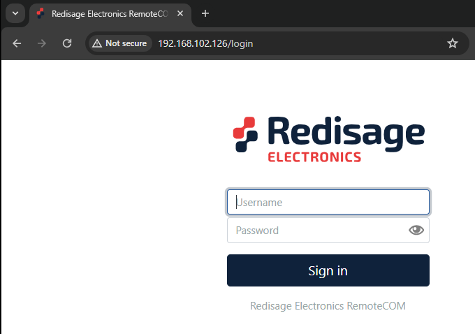
Configuration by the Web Page
Default configuration of the Ethernet Converters:
- IP address: 192.168.100.100
- Subnet mask: 255.255.255.0
- Gateway: 192.168.100.1
- DNS 1: 192.168.100.1
- DNS 2: 8.8.8.8
Default login details:
- User name: admin
- Password: admin123
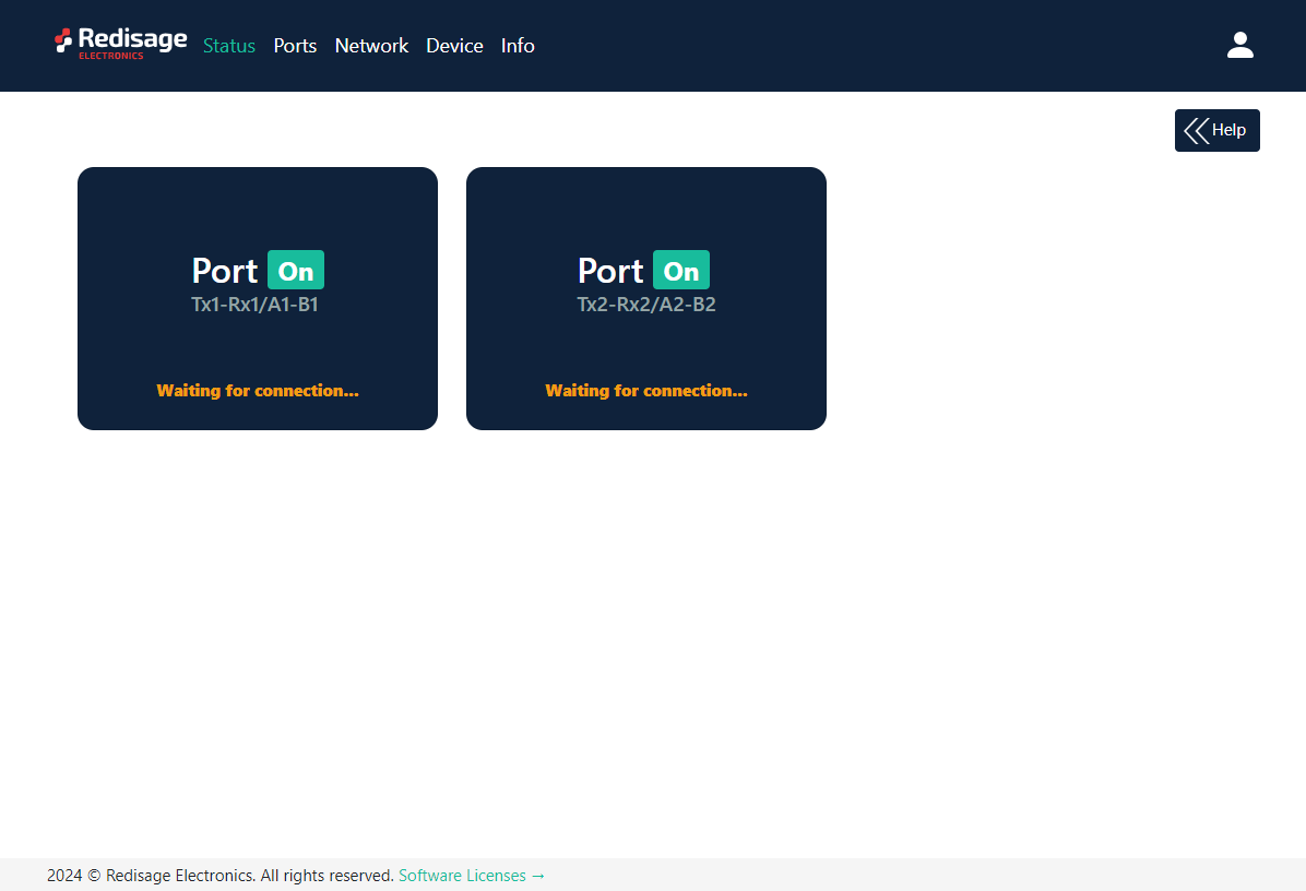
To access to the web page open the web browser, type the IP address in the address bar and log in using the default user name and password. The device and a PC must be connected to the same Local Area Network.
After a successful login, the status page will show the current status of the ports.
To change the user name and password click on the user icon and select “Edit user”.
Ports configuration is available on the “Ports” page.
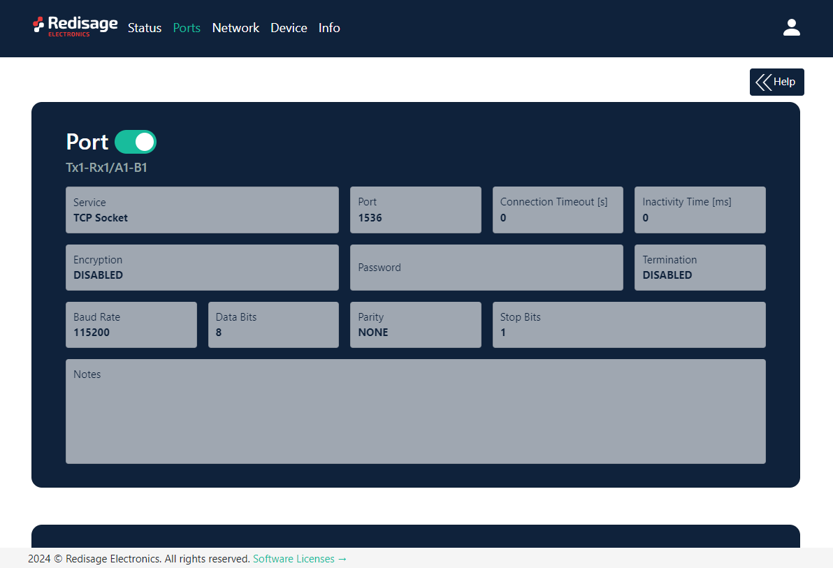
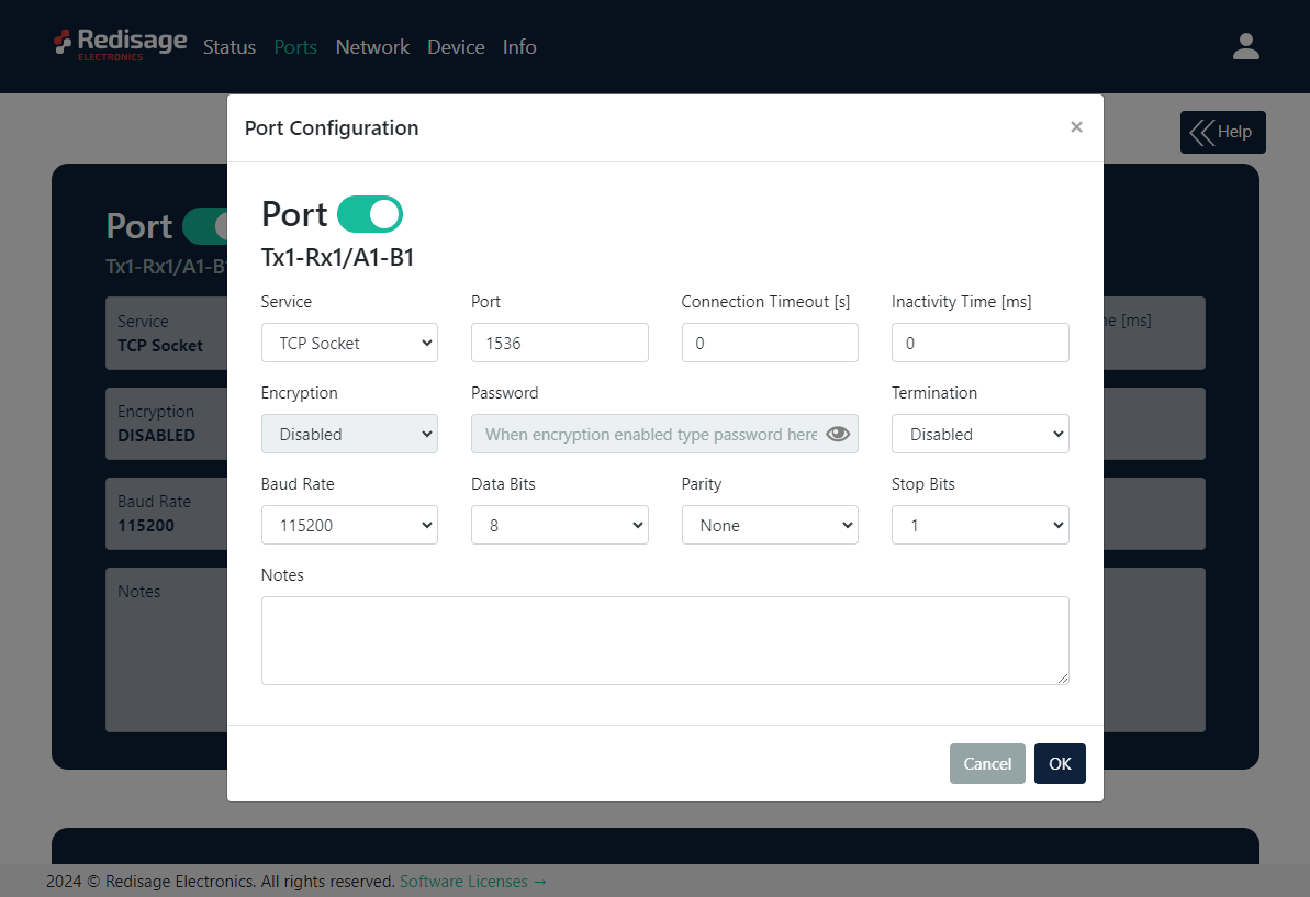
{{@170#bkmrk-item-description-ser}}
Changing port’s service closes all sockets connected to the ports.
In the UDP mode, port number 15051 is reserved for UDP broadcast service.
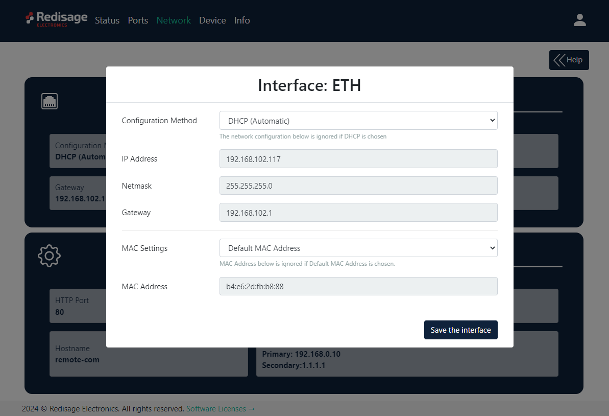
Network settings can be changed on the “Network” page.
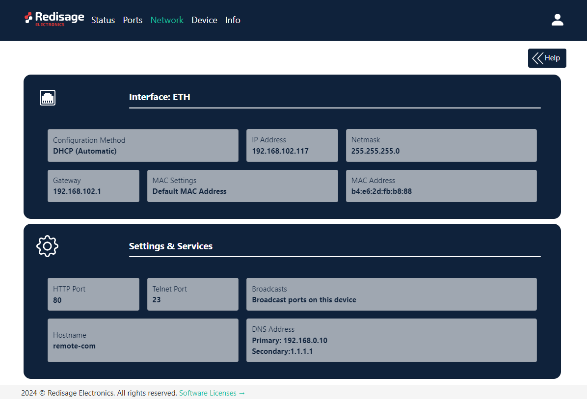
{{@170#bkmrk-item-description-con}}
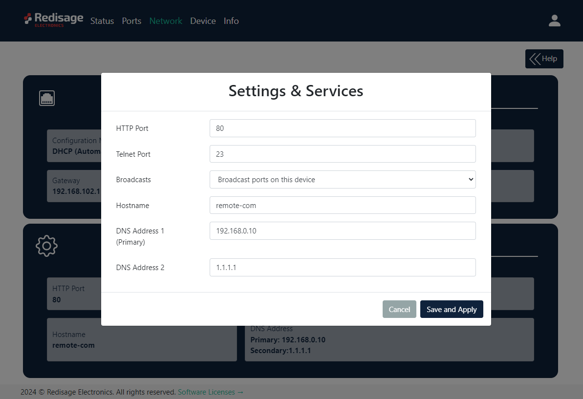
{{@170#bkmrk-item-description-htt}}
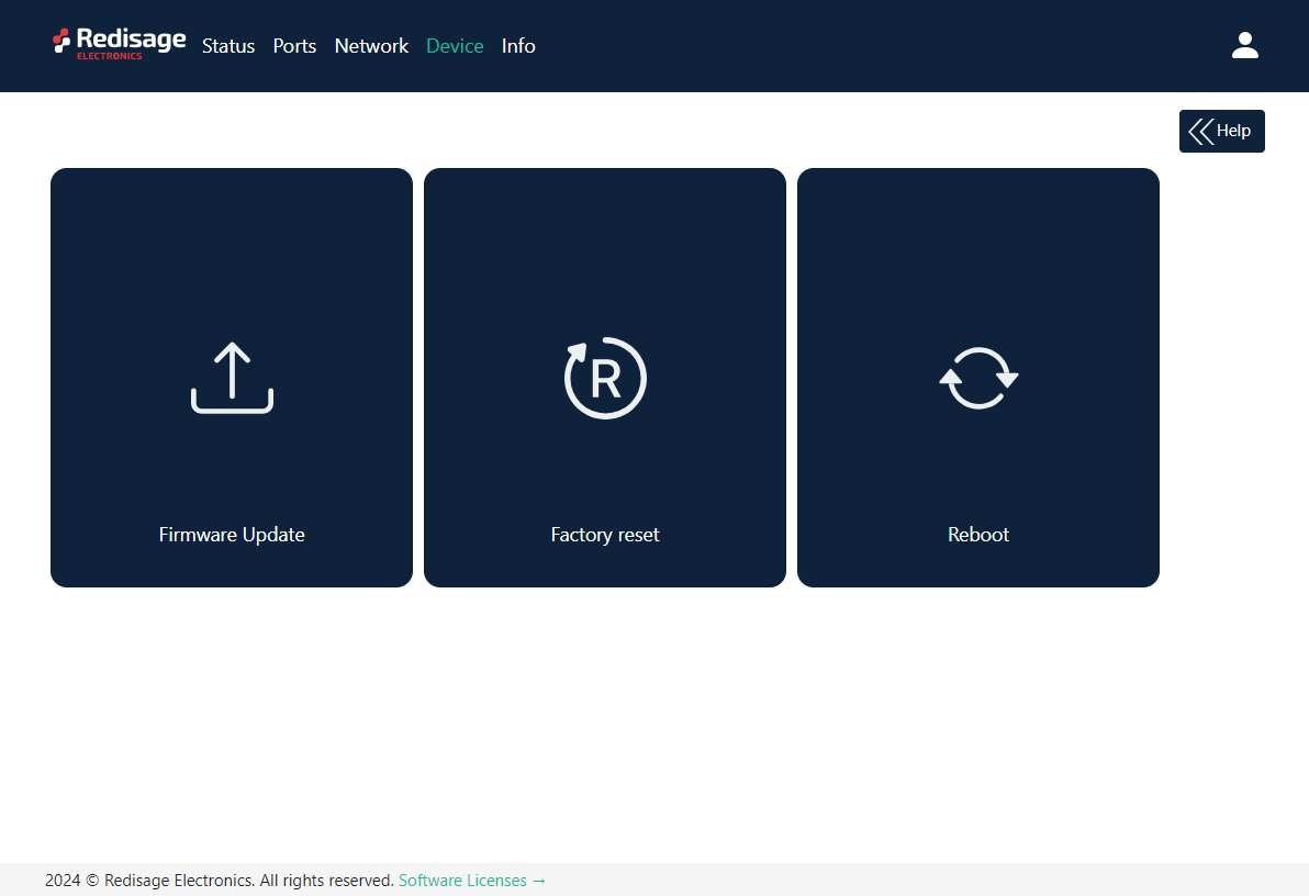
On the “Device” page there are tools used to a firmware update, a factory reset and a device reboot.
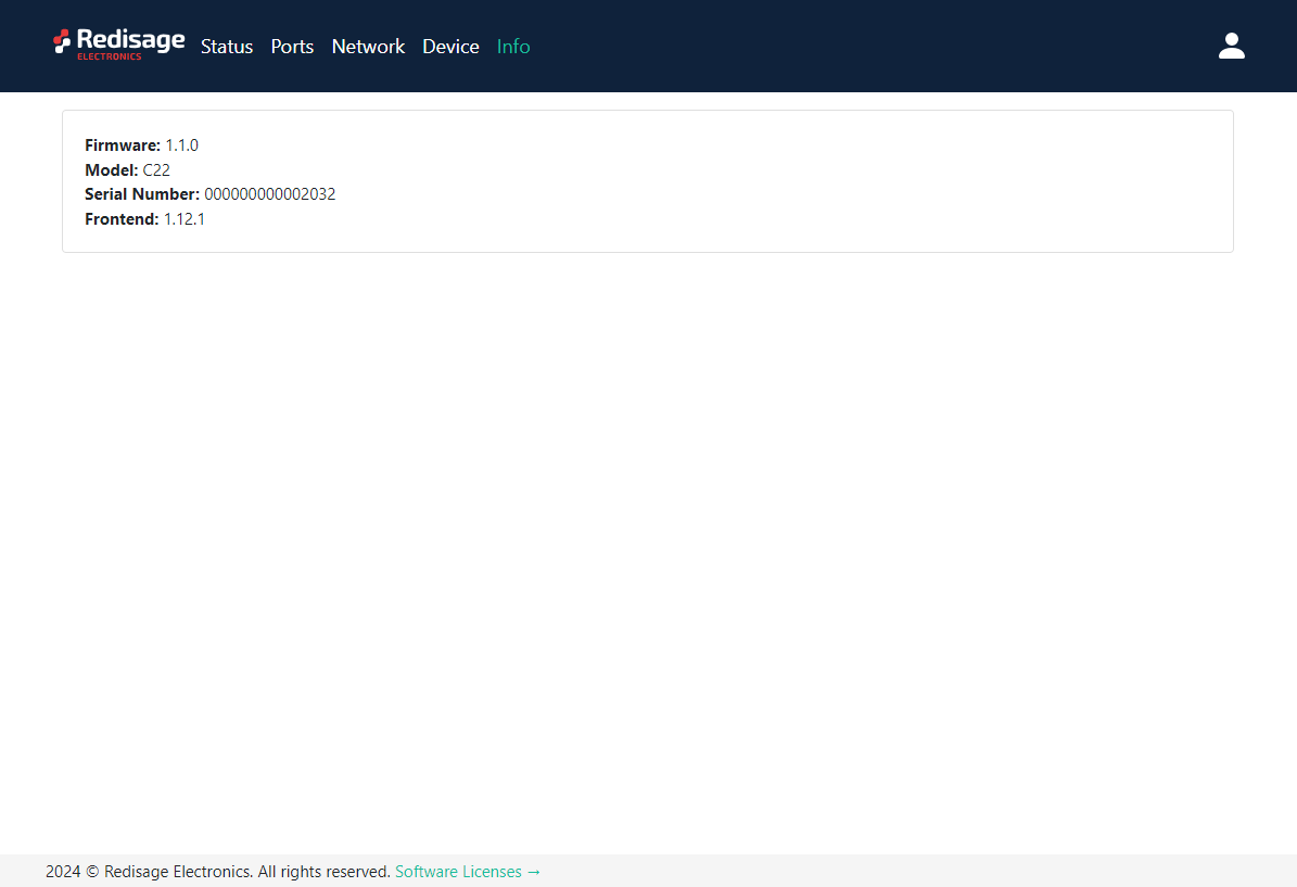
On the “Info” page there is information about firmware, model, serial number and frontend version.
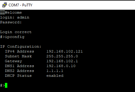
Configuration by Serial Console
The device has the ability to be reconfigured via a serial console. C20 - C22 require a dedicated USB/UART converter connected to the USB micro-B connector on the front of the device. C23 - C25 can be directly connected to a PC through a USB cable.
Procedure to enter serial console mode on C20 - C22.
- Turn off the power of the device.
- Connect the PC to the C1 micro-USB port of Ethernet converter using the dedicated USB/UART converter.
- Open the serial console (default baud rate is 115200 bps).
- Press and hold the S1 button (or connect Din pin to GND pin if the button is not mounted).
- Turn on the power and wait a few seconds until the orange LED lights up.
- Release the button (or disconnect Din pin from GND pin).
Procedure to enter serial console mode on C23 - C25.
- Install STM32 Virtual COM Port Driver.
- Turn off the power of the device.
- Connect the PC to the C1 micro-USB port using the USB cable (or use the dedicated USB/UART converter).
- Open the serial console (default baud rate is 115200 bps).
- Press and hold the S1 button.
- Turn on the power and wait a few seconds until the yellow CN LED lights up.
- Release the button (or disconnect Din pin from GND pin).
Once this is done, log in using the default username and password, then change the network settings using "ipconfig" command.
{{@170#bkmrk-list-of-all-commands}}
{{@170#bkmrk-command-description-}}
{{@171#bkmrk-ports-configuration--1}}
{{@171#bkmrk-in-terms-of-ports-co}}
{{@171#bkmrk-uart-uart-helpprint-}}
{{@171#bkmrk-network-settings}}
{{@171#bkmrk-the-following-comman}}
{{@171#bkmrk-ipconfig-ipconfig-ad}}
{{@171#bkmrk-changing-username-or}}
{{@171#bkmrk-to-change-username-o}}
{{@171#bkmrk-user-helpprint-the-h}}
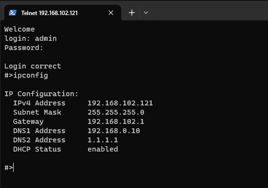
Configuration by Telnet Console
Access to the Telnet console can be obtained using a serial terminal program. Configure the connection type to Telnet, enter the IP address and Telnet port number (23 by default).
Telnet console commands are the same as ones described in the serial console section.
Redisage Configurator
To configure the RemoteCOM ports use the Redisage Configurator program. Redisage Configurator is an app used to emulate a connection between the converter and a PC as if it would be connected directly to the COM port.
Configuration procedure
- Change the device port service to RemoteCOM.
- Set up a port number.
- Enable or disable encryption.
- If encryption is enabled create a password.
- In the Redisage Configurator click add the device and then set the COM number and the service port.
- If encryption is enabled enter a password.
- Click save changes.
- Connect to the configured serial COM port via terminal software.
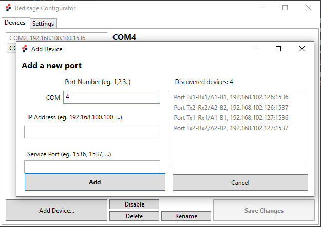
If any change is made to the port configuration, make sure to apply it with the “Save Changes” button.
Reset to factory defaults
Reset to factory defaults is possible on the web page in the device section or using the service mode.
Service mode
Procedure to enter service mode for C20 - C22 converters
- Turn off the power of the device.
- Connect Ethernet converter to the dedicated USB/UART converter via the microUSB port.
- Connect the USB/UART converter to the PC.
- Open the serial console (default baud rate is 115200 bps).
- Press and hold the S1 button.
- Turn on the power.
- Wait until the ST indicator (red LED) lights up.
- Release the S1 button.
- If the process is successful, service commands can be typed into the terminal.
Procedure to enter service mode for C23 - C25 converters
- Install STM32 Virtual COM Port Driver (if it was not done before).
- Turn off the power of the device.
- Connect Ethernet converter directly to the PC (the dedicated USB/UART converter is not obligatory).
- Open the serial console (default baud rate is 115200 bps).
- Press and hold the S1 button.
- Turn on the power.
- Wait until the ST indicator (red LED) lights up.
- Release the S1 button.
- If the process is successful, service commands can be typed into the terminal.
{{@170#bkmrk-list-of-commands-in-}}
{{@170#bkmrk-command-description--1}}
In the service mode, the “ipconfig” command can only show a last static IP address.
{{@168#bkmrk-additional-notes}}
{{@168#bkmrk-products-family-samp}}
{{@168#bkmrk-https%3A%2F%2Fredisage.com}}
{{@168#bkmrk-disclamer-notesall-p}}