Data Sheet
 |
Features
|
Introduction
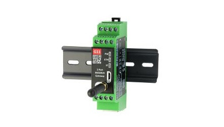
Devices are based on G11 - G13 gateways (ESP32 Xtensa LX6 microcontroller) depending on needed ports and interfaces.
Dedicated EMC integrated circuits guarantee improved connection quality by limiting the impact of interference typical for an industrial environment.
Specification
|
Redisage PN |
G11 |
G12 |
G13 |
||||
|
Ports |
RS232 |
2x |
- |
- |
|||
|
RS485 |
- |
1x |
- |
||||
|
RS232/RS485 |
- |
- |
2x |
||||
|
Microcontroller |
ESP32 |
||||||
|
WiFi |
2.4 GHz b/g/n |
||||||
|
Power |
Voltage |
12-30 VDC |
|||||
|
Power |
< 1 W |
||||||
|
Frame ground connection |
yes |
||||||
|
Baud rate |
up to 115200 bps |
||||||
|
LED indicators |
communication Tx, Rx and power |
||||||
|
RS485 termination |
120 ohm manually enabled |
||||||
|
Connector |
RS232/RS485 |
8-pin terminal block max. 2.5 mm2 wire |
|||||
|
Power |
3-pin terminal block max. 2.5 mm2 wire |
||||||
|
Ethernet |
RJ45 |
||||||
|
Transmission |
RS485 |
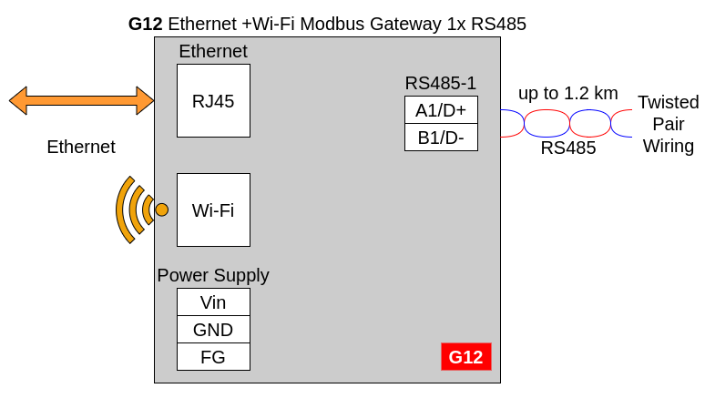
max. 1,200 m at 9.6 kbps; max. 400 m at 115.2 kbps |
|||||
|
RS232 |
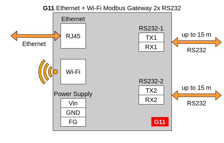
max. 15 m at 115.2 kbps |
||||||
|
Mounting and enclosure |
DIN rail, plastic PA - UL 94 V0, black/green |
||||||
|
Temperatures |
-40°C to +75°C operating and storage |
||||||
|
Humidity |
10 - 90% RH, non-condensing |
||||||
|
ESD protection |
±4 kV contact discharge / ±8 kV air discharge |
||||||
|
Certification |
CE, RoHS |
||||||
Variants
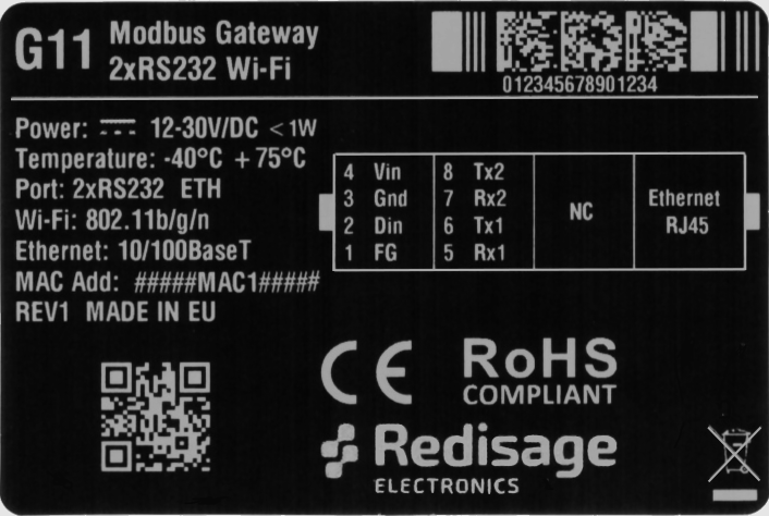
G11 - Ethernet + Wi-Fi Modbus Gateway 2 x RS232
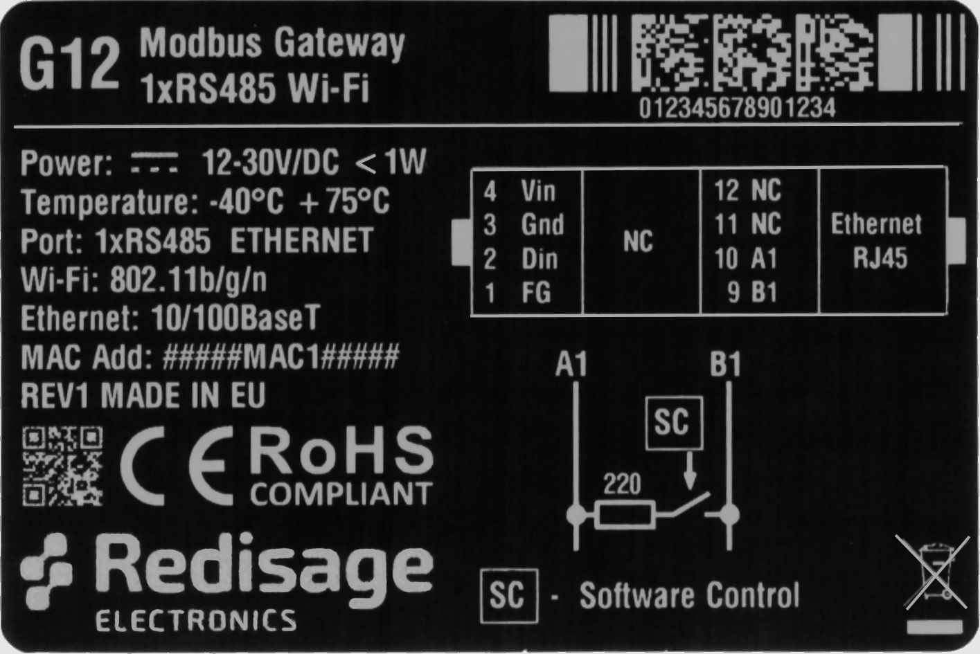
G12 - Ethernet + Wi-Fi Modbus Gateway 1 x RS485
G03 - Ethernet Modbus Gateway 2 x RS232/RS485
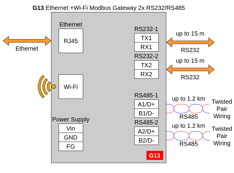
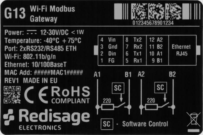
In the G13 gateway user should use only RS232 or only RS485 interface of one port as they occupy the same internal bus of the device.
Frame ground FG
Electronic circuits are constantly prone to electrostatic discharge ESD. Redisage Electronics modules feature a design for the frame ground terminal block FG. The frame ground provides a path for bypassing ESD, which provides enhanced static protection ESD abilities and ensures the module is more reliable. Connecting FG terminal block to the earth ground will bypass the ESD disturbances outside the device so will provide a better level of protection against ESD.
Frame Ground FG connection reference drawing is provided below.
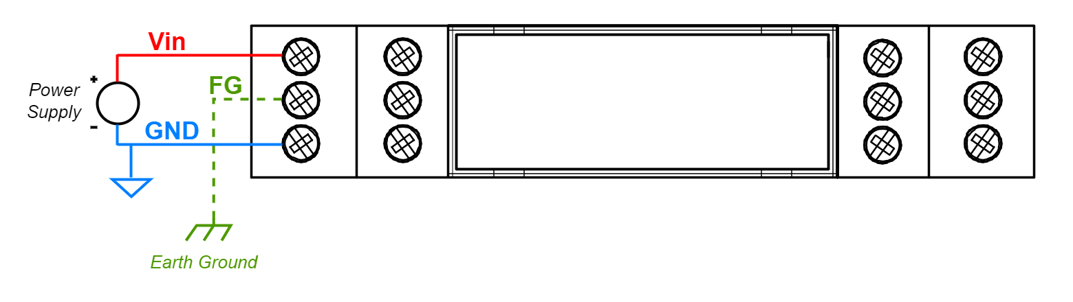
If earth ground is not available FG can be left floating or it can be connected with the power supply GND.
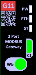
Pin assignments
|
G11
|
G12
|
G13
|
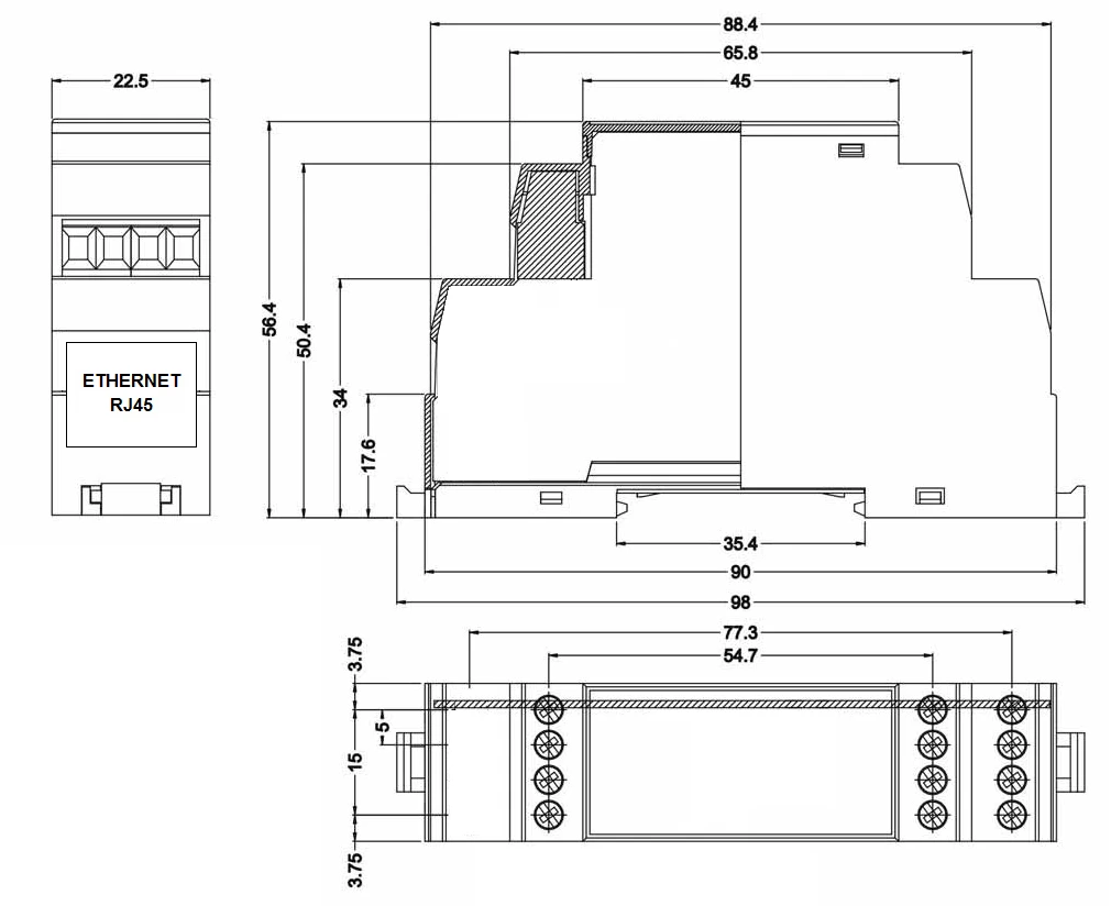
Enclosure dimensions
2U Module Enclosure
98 x 22.5 x 56.4
Units: mm
Getting started
Power supply
Ethernet Modbus gateways G01 - G03 and G14 - G16 have wide voltage power input (12 - 30 VDC). The power consumption is less than 1 W.
LED indicators
Ethernet Modbus gateways G11 - G13 have 3 LED indicators:
- PW LED Blue - Power
- ETH LED Green - Network activity
- ST LED Orange - USB-UART Serial console mode
Additional notes
| Related information and links |
||
| Ordering information | Accessories | Similar products |
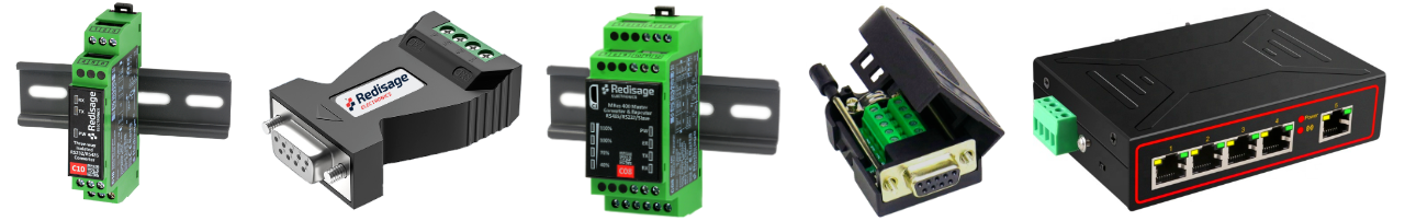
Products family sample photo
DISCLAMER NOTES
ALL PRODUCT, PRODUCT SPECIFICATIONS AND DATA ARE SUBJECT TO CHANGE WITHOUT NOTICE TO IMPROVE RELIABILITY, FUNCTION OR DESIGN OR OTHERWISE.
Datasheet-ID:
SR-D