Data Sheet
Modbus Ethernet Gateways (G01 - G03 & G14 - G16)
|
|
Features
|

Introduction
Devices are based on G01 - G03 gateways (ESP32 Xtensa LX6 microcontroller) and G14 - G16 gateways (STM32F4 microcontroller) depending on needed ports and interfaces.
Dedicated EMC integrated circuits guarantee improved connection quality by limiting the impact of interference typical for an industrial environment.
Modbus gateways allow data transmission between LAN hosts and serial devices by converting Modbus protocols (Modbus TCP and Modbus RTU/ASCII). They are intended to be used in industrial networks especially in the field of Industry 4.0 but not only. Apart from extending the capabilities of industrial devices, they can be also adapted up to user’s requirements and needs.
Transmission is carried out by two modes: Gateway and Router. In the Gateway mode, the port is used to communicate with Slave devices, but in the Router mode with Master devices. It is also possible to set up different modes on every port. Block diagrams below describe how each of these modes works.
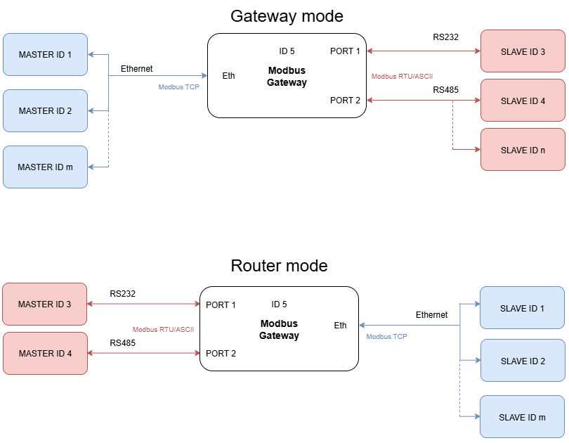
The device has max 20 sockets open in Gateway mode and max 8 in Router mode. It is possible to increase this value at client's request.
{{@175#bkmrk-specification}}
{{@175#bkmrk-redisage-pn-g01-g02-}}
Variants
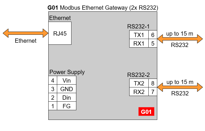
G01 - Ethernet Modbus Gateway 2x RS232
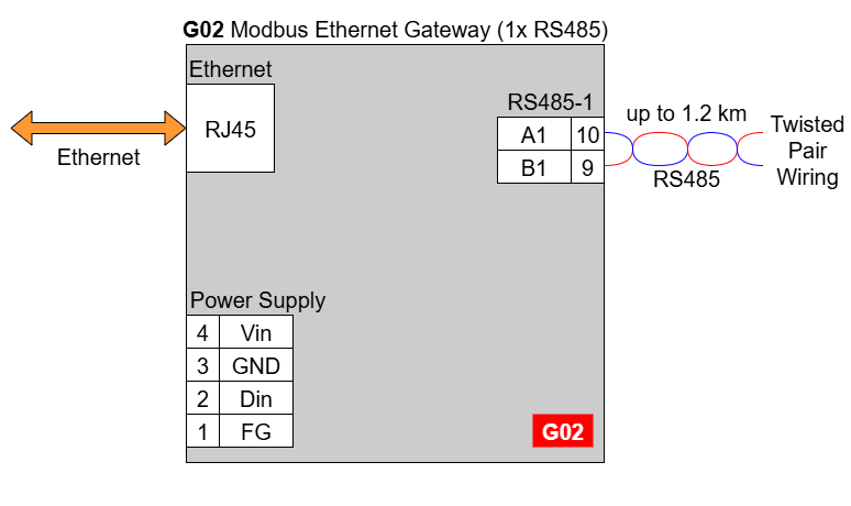
G02 - Ethernet Modbus Gateway 1x RS485
G03 - Ethernet Modbus Gateway 2x RS232/RS485
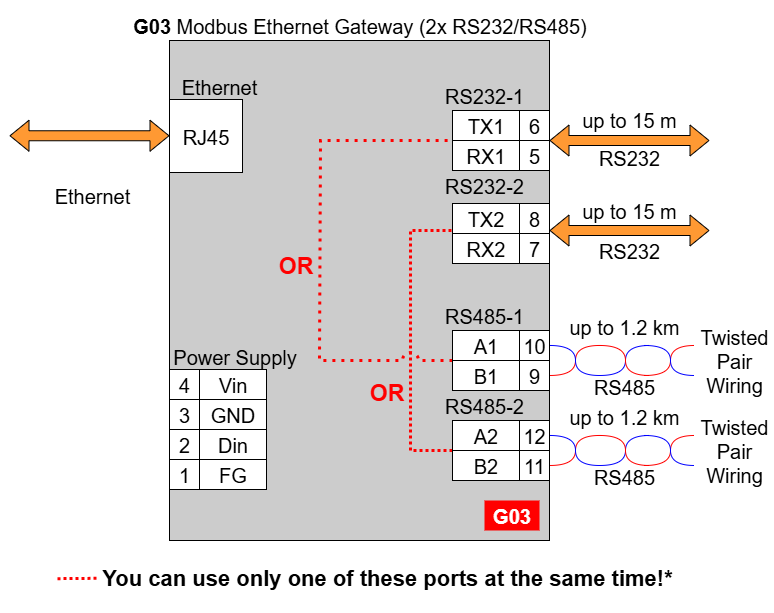
In the G03 gateway user should use only RS232 or only RS485 interface of one port as they occupy the same internal bus of the device. It means, don't use pairs: RS232-1 & RS485-1 at the same time and RS232-2 & RS485-2 at the same time!
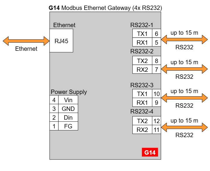
G14 - Ethernet Modbus Gateway 4x RS232
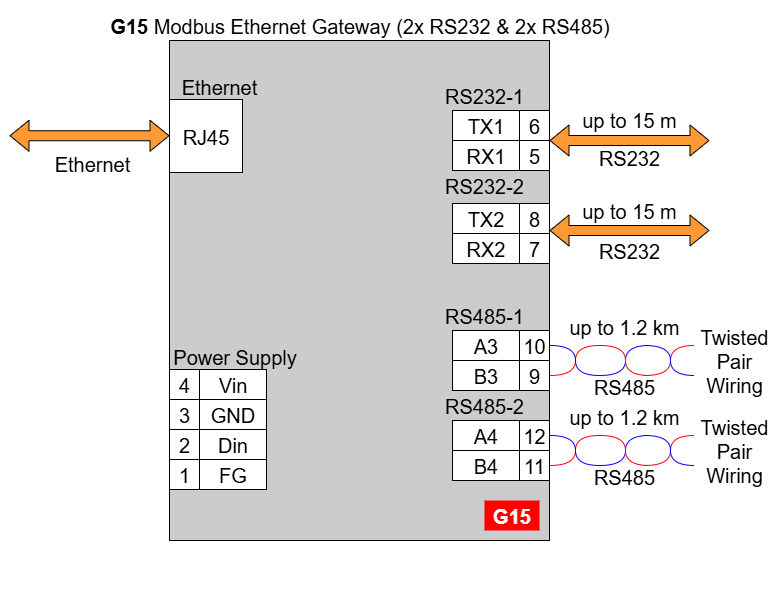
G15 - Ethernet Modbus Gateway 2x RS232 & 2x RS485
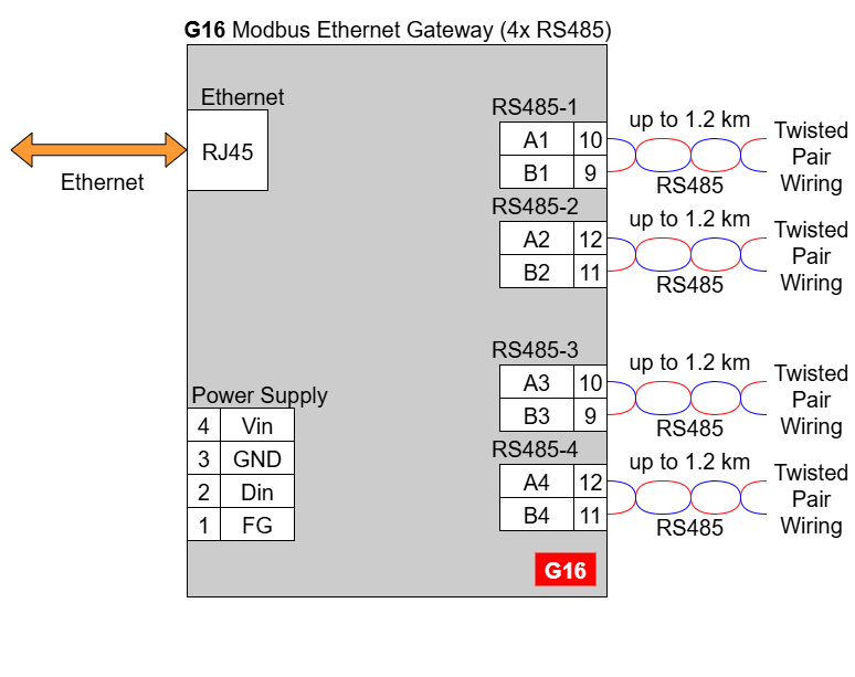
G16 - Ethernet Modbus Gateway 4x RS485
{{@169}}
{{@175#bkmrk-pin-assignments}}
{{@175#bkmrk-g01-g02-g03-g14-g15-}}
LED indicators
|
Modbus Gateways G01 - G03 |
Modbus Gateways G14 - G16 |
||||
 |
 |
||||
|
LED indicator |
Color |
Function |
LED indicator |
Color |
Function |
|---|---|---|---|---|---|
|
PW |
Blue |
Power |
PW |
Blue |
Power |
|
ETH |
Green |
Network activity |
ETH |
Green |
Network activity |
|
ST |
Orange |
Console mode |
CN |
Yellow |
Console mode |
|
Red |
Service mode |
COM |
Green |
RS232/RS485 activity |
|
|
|
SR |
Red |
Service mode |
||
|
ER |
Yellow |
Error |
|||
{{@221#bkmrk-enclosure-dimensions-2}}
{{@221#bkmrk-2u-module-enclosure9-1}}
{{@221#bkmrk--2}}
Pin assignments
Reset to Factory Defaults
Reset to factory defaults is possible on the web page in the device section or using the service mode.
Service mode
{{@177#bkmrk-procedure-to-enter-s-2}}
{{@177#bkmrk-turn-off-the-power-o-1}}
{{@177#bkmrk-procedure-to-enter-s-3}}
{{@177#bkmrk-install-stm32-virtua-1}}
{{@175#bkmrk-list-of-commands-in-}}
{{@175#bkmrk-command-description--1}}
{{@175#bkmrk-in-the-service-mode%2C}}
{{@168}}
SR-D