External Interfaces
USB
The device is equipped with 2 USB connectors.
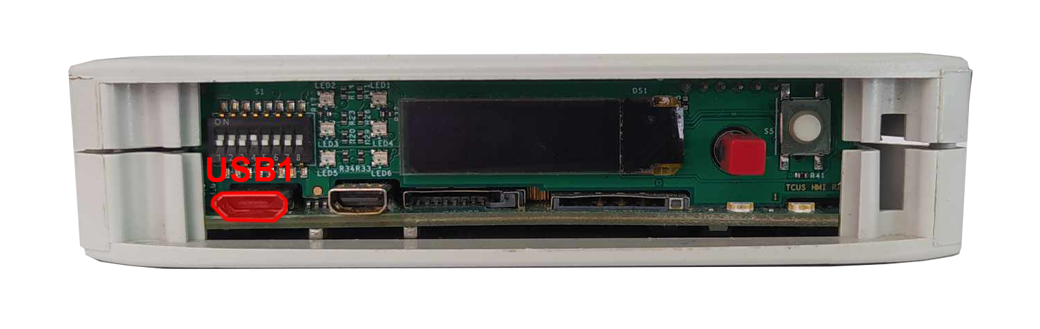
USB1
MicroUSB connector for USB 2.0 is placed on the front panel. The interface can work in both host and device modes. The signal on the connector can be chosen with a switch. Maximum current of the connector is 500 mA.
MicroUSB connector location
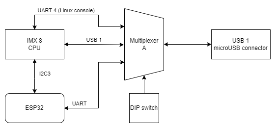
USB 1 connection diagram
|
Function |
Processor pin |
Default function |
|---|---|---|
|
5 V USB voltage |
F22 |
USB1_VBUS |
|
USB data differential pair negative |
A22 |
USB1_D_N |
|
USB data differential pair positive |
B22 |
USB1_D_P |
|
USB on the go |
AB10 |
USB1_OTG_PWR |
USB2
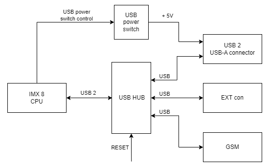
USB-A connector for USB 2.0 is placed on a side of the device with the interface set up in a host mode. Maximum current of the connector is 1 A.
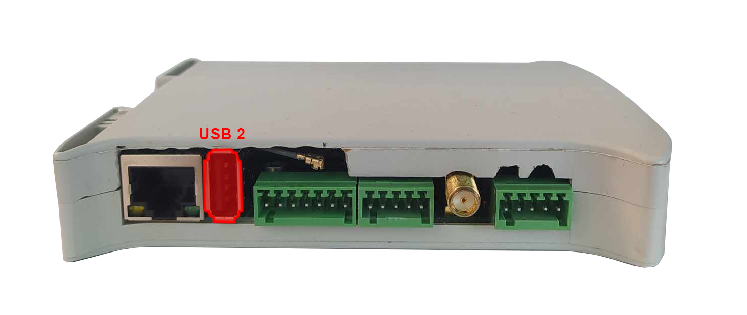
USB 2 connection diagram
|
Function |
Processor pin |
Default function |
|---|---|---|
|
USB power switch control |
F23 |
USB2_VBUS |
|
USB data differential pair negative |
A23 |
USB2_D_N |
|
USB data differential pair positive |
B23 |
USB2_D_P |
Serial ports
The device is equipped with 3 serial port connectors.
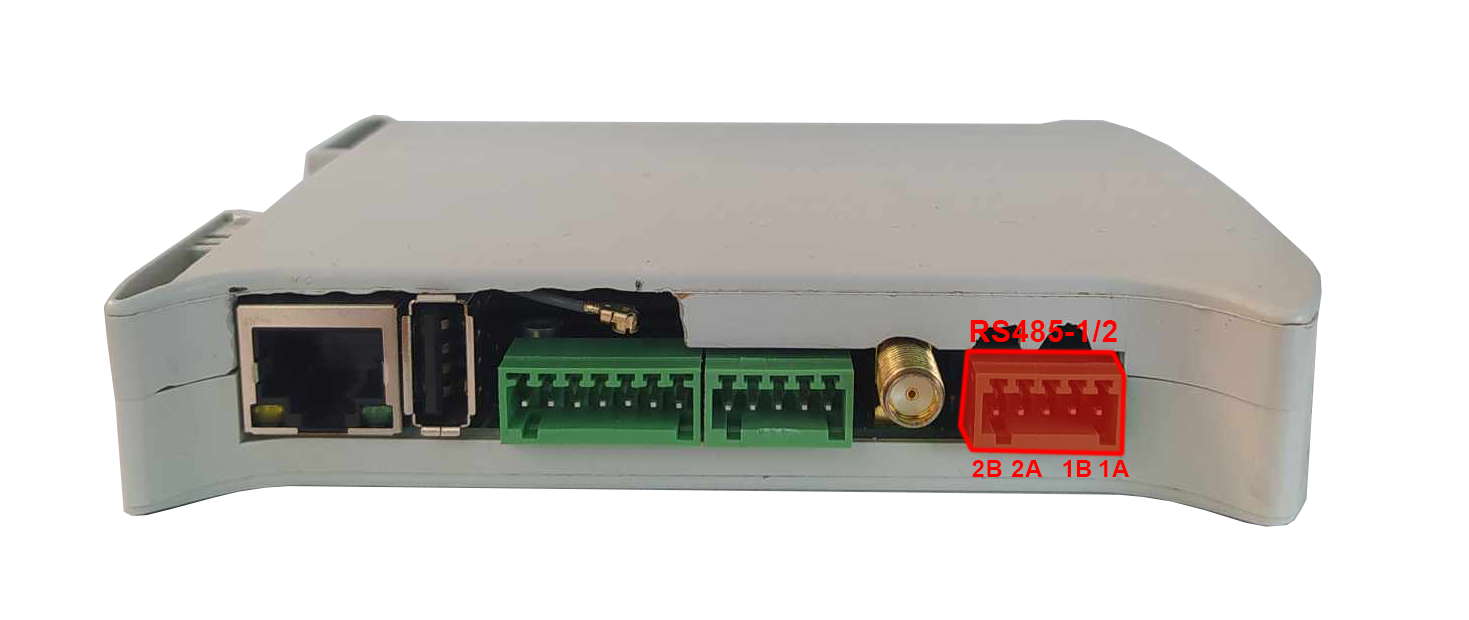
RS485-1/2
Baud rate: 50-115200 bps.
Location of the RS485-1/2 connector
|
Connector pin |
Description |
|---|---|
|
A1 |
RS485 A1 |
|
B1 |
RS485 B1 |
|
G |
Ground |
|
A2 |
RS485 A2 |
|
B2 |
RS485 B2 |
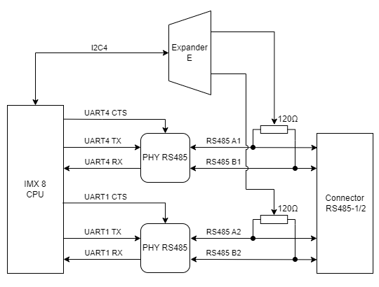
RS485-1/2 connections diagram
{{@134#bkmrk-uart4}}
{{@134#bkmrk-device-name%3A-%2Fdev%2Ftt-2}}
{{@134#bkmrk-signal-processor-pin-6}}
{{@134#bkmrk-uart-1}}
{{@134#bkmrk-device-name%3A-%2Fdev%2Ftt}}
{{@134#bkmrk-signal-processor-pin-4}}
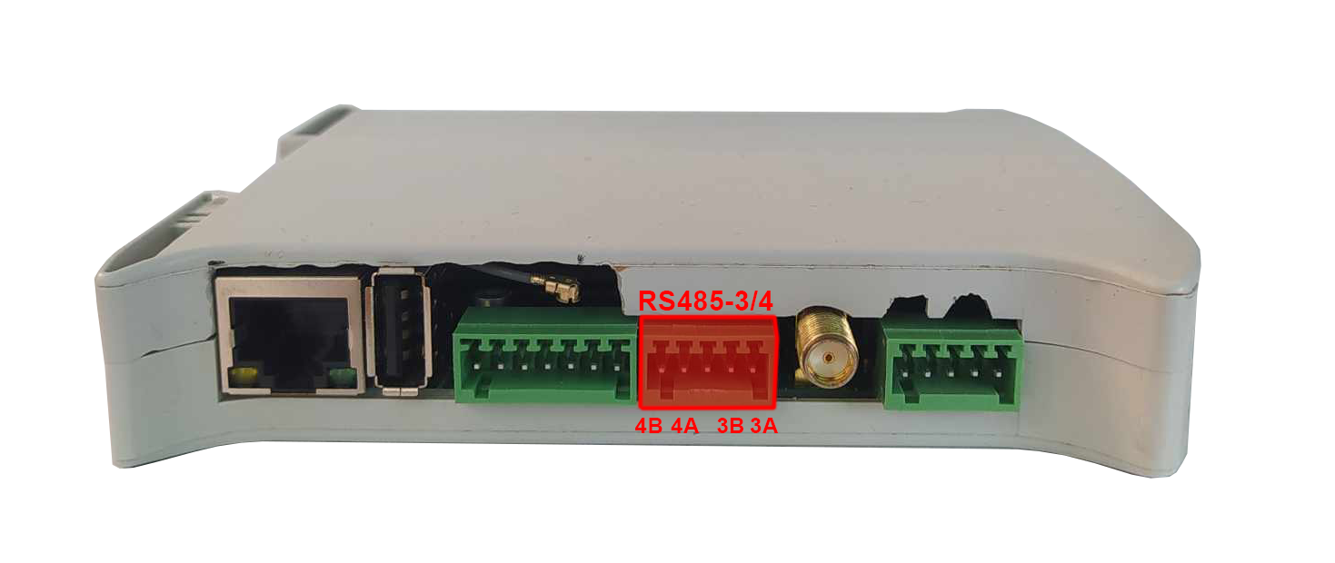
RS485-3/4
Baud rate: 50-115200 bps.
Location of the RS485-3/4 connector
|
Connector pin |
Description |
|---|---|
|
A3 |
RS485 A3 |
|
B3 |
RS485 B3 |
|
G |
Ground |
|
A4 |
RS485 A4 |
|
B4 |
RS485 B4 |
RS485-3/4 connections diagram
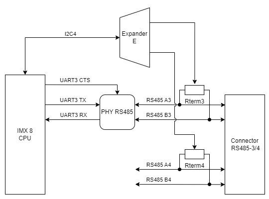
{{@134#bkmrk-uart3}}
{{@134#bkmrk-device-name%3A-%2Fdev%2Ftt-2}}
{{@134#bkmrk-signal-processor-pin-6}}
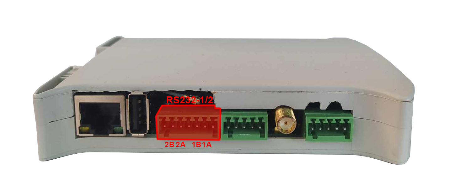
RS232-1/2
Baud rate: 50-115200 bps.
Location of the RS232-1/2 connector
|
Connector pin |
Description |
|---|---|
|
T1 |
RS232 TX1 |
|
R1 |
RS232 RX1 |
|
T2 |
RS232 TX2 |
|
R2 |
RS232 RX2 |
RS232-1/2 connections diagram
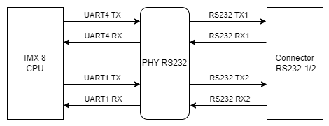
{{@134#bkmrk-uart4}}
{{@134#bkmrk-device-name%3A-%2Fdev%2Ftt-2}}
{{@134#bkmrk-signal-processor-pin-6}}
{{@134#bkmrk-uart-1}}
{{@134#bkmrk-device-name%3A-%2Fdev%2Ftt}}
{{@134#bkmrk-signal-processor-pin-4}}
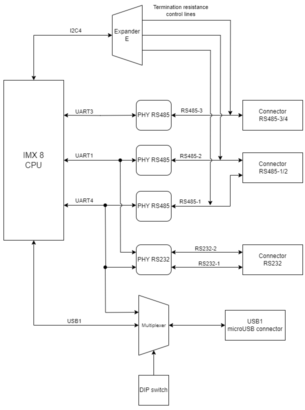
Expander E
The termination resistors are controlled by signals output from the Expander E connected by I2C4 interface with the CPU.
Diagram of serial ports connections
1-Wire
The device is equipped with the 1-Wire interface operating with Maxim sensors. Connector 5 V outputs are secured with a 100 mA fuse.
1-Wire connector and pins
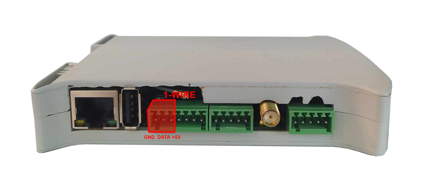
| Connector pin |
Description |
|---|---|
|
1W |
1-Wire data |
|
5V |
1-Wire +5 V power |
|
G |
Ground |
1-Wire connection diagram
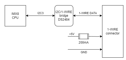
{{@134#bkmrk-i2c3}}
{{@134#bkmrk-device-name%3A-%2Fdev%2Fi2}}
{{@134#bkmrk-signal-processor-pin-2}}
1-Wire bridge
Part number: DS2484
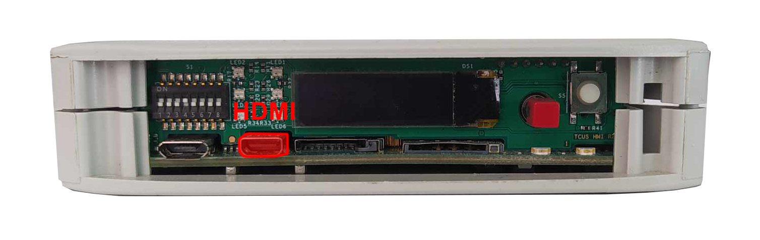
HDMI
The device is equipped with the microHDMI standard connector located on the front panel.
HDMI connector location
|
Signal |
Processor pin |
Default function |
|---|---|---|
|
DSI_TX0_N |
A9 |
MIPI_DSI_TX0_N |
|
DSI_TX0_P |
B9 |
MIPI_DSI_TX0_P |
|
DSI_TX1_N |
A10 |
MIPI_DSI_TX1_N |
|
DSI_TX1_P |
B10 |
MIPI_DSI_TX1_P |
|
DSI_TX2_N |
A12 |
MIPI_DSI_TX2_N |
|
DSI_TX2_P |
B12 |
MIPI_DSI_TX2_P |
|
DSI_TX3_N |
A13 |
MIPI_DSI_TX3_N |
|
DSI_TX3_P |
B13 |
MIPI_DSI_TX3_P |
|
DSI_CLK_N |
A11 |
MIPI_DSI_CLK_N |
|
DSI_CLK_P |
B11 |
MIPI_DSI_CLK_P |
HDMI connection diagram
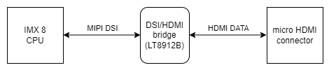

DSI/HDMI Bridge
Part number: LT8912B
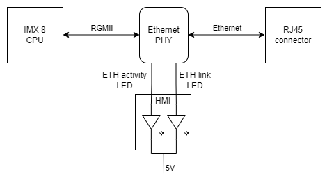
ETHERNET
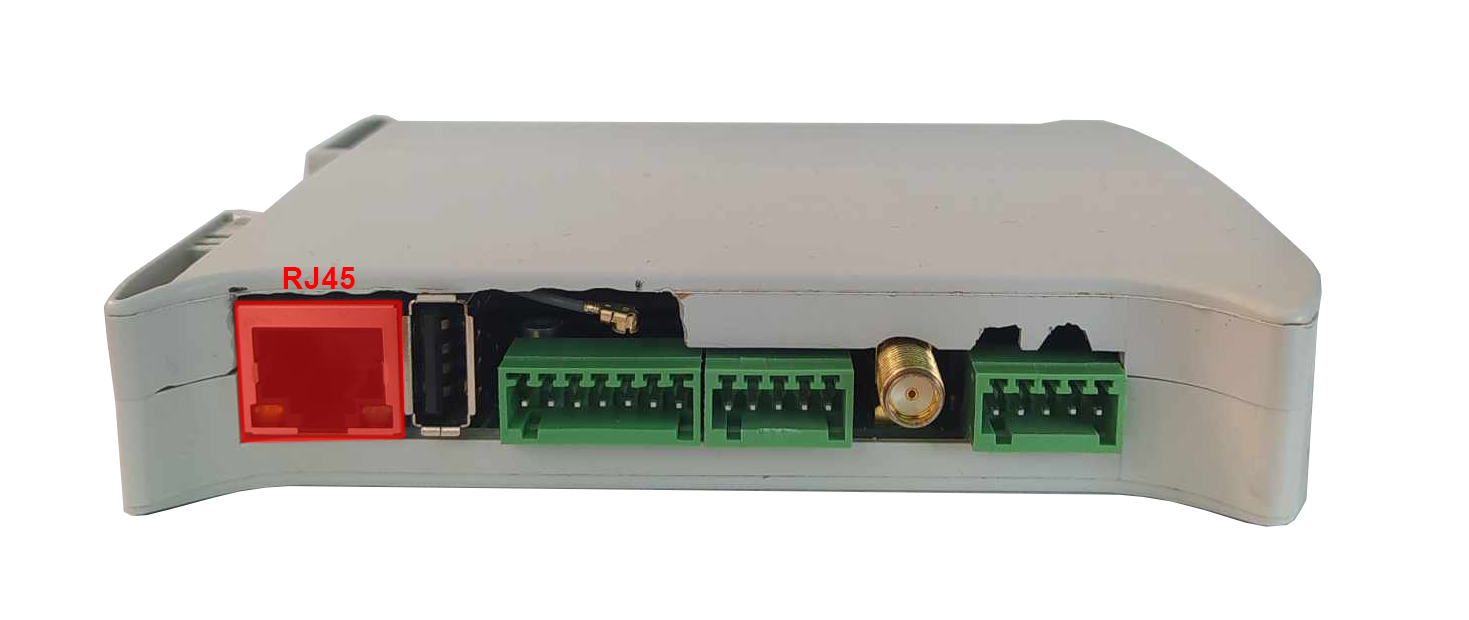
The device is equipped with a RJ45 connector placed on the side of the device. Diode on the front panel signals ETHERNET's operation.
RJ45 connector location
Ethernet connection diagram