External Interfaces
DIO_ReadDIO read
This example shows how to use DIO (Digital Input Output) of the Tiger computer in the read mode. After running the program, the state of the every DIO will be displayed.
Connections
In order to test the program use H1 - H7 pins (diagram provided onat the bottom of this page).
DIO_WriteDIO write
This example shows how to use DIO (Digital Input Output) of the Tiger computer in the write mode.
Connections
In order to test the program use H1 - H7 pins (diagram provided onat the bottom of this page).
DI_ReadDI read
This example shows how to read statethe states of the DI (Digital Input) of the Tiger computer. After running the program, the state of the every DI will be displayed.
Connections
In order to test the program use D1 - D5 pins (diagram provided onat the bottom of this page).
ETHERNET
This example shows how to check the Ethernet port connection of the Tiger computer.
- ETHERNET - C example
- ETHERNET - Python example
- ETHERNET - Bash example
Connections
In order to test the program use the RJ45 port (diagram provided onat the bottom of this page).
ONEWIRE1-WIRE
This example shows how to read temperature from the DS18B20+ sensor using the 1-Wire bus of the Tiger computer.
- ONEWIRE - C example
- ONEWIRE - Python example
- ONEWIRE - Bash example
Connections
In order to test the program use 1W, 5V and GND pins (diagram provided onat the bottom of this page).
RS232
This example shows how to write to and read from the RS232 interface of the Tiger computer.
- RS232 - C example
- RS232 - Python example
- RS232 - Bash example
This example won’t work in the loopback connection test.
Connections
In order to test the program use T1, R1, T2, R2 and GND pins (diagram provided onat the bottom of this page).
RS485
This example shows how to write to and read from the RS485 interface of the Tiger computer.
- RS485 - C example
- RS485 - Python example
- RS485 - Bash example
This example won’t work in the loopback connection test.
Connections
In order to test the program use A1 - A4, B1 - B4 and GND pins (diagram provided onat the bottom of this page).
UIO_AI_10VUIO AI 10 V
This example shows how to use the UIO (Universal Input Output) of the Tiger computer as a voltage AI (Analog Input).
- UIO_AI_10V - C example
- UIO_AI_10V - Python example
- UIO_AI_10V - Bash example
Connections
In order to test the program use U1 - U4 pins (diagram provided onat the bottom of this page).
UIO_AI_20mAUIO AI 20 mA
This example shows how to use the UIO (Universal Input Output) of the Tiger computer as a current AI (Analog Input).
- UIO_AI_20mA - C example
- UIO_AI_20mA - Python example
- UIO_AI_20mA - Bash example
Connections
In order to test the program use U1 - U4 pins (diagram provided onat the bottom of this page).
UIO_AOUIO AO
This example shows how to use the UIO (Universal Input Output) of the Tiger computer as an AO (Analog Output).
- UIO_AO - C example
- UIO_AO - Python example
- UIO_AO - Bash example
Connections
In order to test the program use U1 - U4 pins (diagram provided onat the bottom of this page).
UIO_DIUIO DI
This example shows how to use the UIO (Universal Input Output) of the Tiger computer as a DI (Digital Input).
- UIO_DI - C examples
- UIO_DI - Python example
- UIO_DI - Bash example
Connections
In order to test the program use U1 - U4 pins (diagram provided onat the bottom of this page).
USB
This example shows how to open, write toto, and read from a USB device plugged into the Tiger computer.
- USB - C example
- USB - Python example
- USB - Bash example
Connections
In order to test the program use the USB port (diagram provided onat the bottom of this page).
WIFI
This example showshows how to connect the Tiger computer to a WiFi access point.
- WIFI - C example
- WIFI - Python example
- WIFI - Bash example
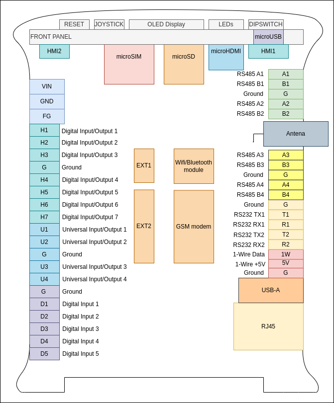
Ports diagram