Expanders
Tiger City IMX Industrial Computer with Linux OS
Expander A
Part number: 74HC595BQ
Expander A diagram
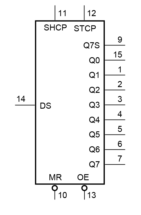
Expander A pins description
|
Pin |
Type |
Usage |
User-space name |
Description |
|
1 |
Q1 |
DO1 |
gpiochip8 1 |
Digital output 1 |
|
2 |
Q2 |
DO2 |
gpiochip8 2 |
Digital output 2 |
|
3 |
Q3 |
DO3 |
gpiochip8 3 |
Digital output 3 |
|
4 |
Q4 |
DO4 |
gpiochip8 4 |
Digital output 4 |
|
5 |
Q5 |
DO5 |
gpiochip8 5 |
Digital output 5 |
|
6 |
Q6 |
DO6 |
gpiochip8 6 |
Digital output 6 |
|
7 |
Q7 |
DO7 |
gpiochip8 7 |
Digital output 7 |
|
9 |
Q7S |
NC |
X |
First shift register signal |
|
10 |
MR/ |
NRST_GLOBAL |
X |
Reset |
|
11 |
SHCP |
SPI1_SCLK |
X |
SPI clock |
|
12 |
STCP |
SPI1_CS1 |
X |
SPI chip select |
|
13 |
OE/ |
GND |
X |
Output enable |
|
14 |
DS |
SPI1_MOSI |
X |
SPI master out slave in |
|
15 |
Q0 |
MUX_DIO_SEL |
gpiochip8 0 |
MUX_PWM selection signal |
|
16 |
VCC |
+3V3 |
X |
Power supply |
SPI1
|
Signal |
Processor pin |
Default function |
|
Chip select 0 |
AD18 |
SPI1_CS0 |
|
Chip select 1 |
AG23 |
SPI1_CS1 |
|
Master in slave out |
A7 |
SPI1_MISO |
|
Clock |
D6 |
SPI1_SCLK |
|
Master out slave in |
B7 |
SPI1_MOSI |
Expander B
Part number: (...)
Expander B diagram
(...)
Expander B pins description
(...)
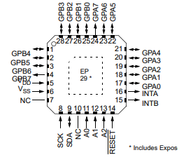
Expander C
Part number: MCP23017-E/ML
Expander C diagram

Expander C pins description
|
Pin |
Port |
Type |
User-space name |
Description |
|
17 |
GPA0 |
GPO |
gpiochip6 0 |
UIO3 configuration |
|
18 |
GPA1 |
GPO |
gpiochip6 1 |
UIO3 configuration |
|
19 |
GPA2 |
GPO |
gpiochip6 2 |
UIO1 configuration |
|
20 |
GPA3 |
GPO |
gpiochip6 3 |
UIO1 configuration |
|
21 |
GPA4 |
GPO |
gpiochip6 4 |
UIO1 configuration |
|
22 |
GPA5 |
GPO |
gpiochip6 5 |
UIO2 configuration |
|
23 |
GPA6 |
GPO |
gpiochip6 6 |
UIO3 configuration |
|
24 |
GPA7 |
GPO |
gpiochip6 7 |
UIO4 configuration |
|
25 |
GPB0 |
GPO |
gpiochip6 8 |
UIO4 configuration |
|
26 |
GPB1 |
GPO |
gpiochip6 9 |
UIO4 configuration |
|
27 |
GPB2 |
GPO |
gpiochip6 10 |
UIO1 configuration |
|
28 |
GPB3 |
GPO |
gpiochip6 11 |
UIO2 configuration |
|
|
|
|
|
|
|
1 |
GPB4 |
GPIO |
gpiochip6 12 |
UIO4 voltage |
|
2 |
GPB5 |
GPIO |
gpiochip6 13 |
UIO4 current |
|
3 |
GPB6 |
GPIO |
gpiochip6 14 |
UIO4 resistance |
|
4 |
GPB7 |
GPIO |
gpiochip6 15 |
UIO3 resistance |
|
5 |
VDD |
+3V3 |
X |
Power supply |
|
6 |
VSS |
GND |
X |
Ground |
|
7 |
NC |
NC |
X |
Not connected |
|
8 |
SCK |
GPIO |
X |
I2C2 clock |
|
9 |
SDA |
GPIO |
X |
I2C2 data |
|
12 |
A1 |
+3V3 |
X |
Address bit 1 |
|
13 |
A2 |
GND |
X |
Address bit 2 |
|
14 |
RESET/ |
EXP1_NRST |
X |
Reset |
|
15 |
INTB |
GPIO_EXP_INT |
X |
Interrupt B |
|
16 |
INTA |
GPIO_EXP_INT |
X |
Interrupt A |
I2C2
Device name: /dev/i2c-1
|
Signal |
Processor pin |
Default function |
|
Clock |
D10 |
I2C2_SCL |
|
Data |
D9 |
I2C2_SDA |
Expander D
Part number: MCP23017
Expander D diagram
Expander D pins description
|
Pin |
Port |
Type |
User-space name |
Description |
|
17 |
GPA0 |
GPI |
gpiochip7 0 |
Joystick left input |
|
18 |
GPA1 |
GPI |
gpiochip7 1 |
Joystick up input |
|
19 |
GPA2 |
GPI |
gpiochip7 2 |
Joystick down input |
|
20 |
GPA3 |
GPI |
gpiochip7 3 |
Joystick right input |
|
21 |
GPA4 |
GPI |
gpiochip7 4 |
Joystick push input |
|
22 |
GPA5 |
GPO |
gpiochip7 5 |
LED3 RED ON/OFF |
|
23 |
GPA6 |
GPI |
gpiochip7 6 |
Dipswitch_1 input |
|
24 |
GPA7 |
GPI |
gpiochip7 7 |
Dipswitch_2 input |
|
25 |
GPB0 |
GPI |
gpiochip7 8 |
Dipswitch_3 input |
|
26 |
GPB1 |
GPO |
gpiochip7 9 |
LED 5 V power supply ON/OFF |
|
27 |
GPB2 |
GPO |
gpiochip7 10 |
LED3 GREEN ON/OFF |
|
28 |
GPB3 |
GPO |
gpiochip7 11 |
LED4 RED ON/OFF |
|
1 |
GPB4 |
GPO |
gpiochip7 12 |
LED3 BLUE ON/OFF |
|
2 |
GPB5 |
GPO |
gpiochip7 13 |
LED4 GREEN ON/OFF |
|
3 |
GPB6 |
GPO |
gpiochip7 14 |
OLED ON/OFF |
|
4 |
GPB7 |
GPO |
gpiochip7 15 |
LED4 BLUE ON/OFF |
I2C3
Device name: /dev/i2c-2
|
Signal |
Processor pin |
Default function |
|
Clock |
E10 |
I2C3_SCL |
|
Data |
F10 |
I2C3_SDA |
Expander E
Part number: MCP23017-E/ML
Expander E diagram

Expander E pins description
|
Pin |
Port |
Type |
User-space name |
Description |
|
1 |
GPB4 |
GPI |
gpiochip5 12 |
Digital input 4 (DIO circuit) |
|
2 |
GPB5 |
GPI |
gpiochip5 13 |
Digital input 5 (DIO circuit) |
|
3 |
GPB6 |
GPI |
gpiochip5 14 |
Digital input 6 (DIO circuit) |
|
4 |
GPB7 |
GPI |
gpiochip5 15 |
Digital input 7 (DIO circuit) |
|
5 |
VDD |
+3V3 |
X |
Power supply |
|
6 |
VSS |
GND |
X |
Ground |
|
7 |
NC |
NC |
X |
Not connected |
|
8 |
SCK |
GPIO |
X |
I2C3 clock |
|
9 |
SDA |
GPIO |
X |
I2C3 data |
|
10 |
NC |
NC |
X |
Not connected |
|
11 |
A0 |
+3V3 |
X |
Address bit 0 |
|
12 |
A1 |
+3V3 |
X |
Address bit 1 |
|
13 |
A2 |
GND |
X |
Address bit 2 |
|
14 |
RESET/ |
EXP1_NRST |
X |
Reset |
|
15 |
INTB |
GPIO_EXP_INT |
X |
Interrupt B |
|
16 |
INTA |
GPIO_EXP_INT |
X |
Interrupt A |
|
17 |
GPA0 |
GPO |
gpiochip5 0 |
Termination RS485_4 ON/OFF |
|
18 |
GPA1 |
GPO |
gpiochip5 1 |
Termination RS485_3 ON/OFF |
|
19 |
GPA2 |
GPO |
gpiochip5 2 |
Termination RS485_2 ON/OFF |
|
20 |
GPA3 |
GPO |
gpiochip5 3 |
Termination RS485_1 ON/OFF |
|
21 |
GPA4 |
NC |
X |
Not connected |
|
22 |
GPA5 |
NC |
X |
Not connected |
|
23 |
GPA6 |
GPO |
gpiochip5 6 |
Secure chip idle/busy |
|
24 |
GPA7 |
GPI |
gpiochip5 7 |
Digital input 1 (DIO circuit) |
|
25 |
GPB0 |
GPO |
gpiochip5 8 |
Digital input 2 (DIO circuit) |
|
26 |
GPB1 |
GPI |
gpiochip5 9 |
SD detect |
|
27 |
GPB2 |
GPI |
gpiochip5 10 |
VIN level error |
|
28 |
GPB3 |
GPI |
gpiochip5 11 |
Digital input 3 (DIO circuit) |
I2C3
Device name: /dev/i2c-2
|
Signal |
Processor pin |
Default function |
|
Clock |
E10 |
I2C3_SCL |
|
Data |
F10 |
I2C3_SDA |