Data Sheet
Modbus gateways allow data transmission between LAN hosts and serial devices by converting Modbus protocols (Modbus TCP and Modbus RTU/ASCII). They are intended to be used in industrial networks especially in the field of Industry 4.0 but not only. Apart from extending the capabilities of industrial devices, they can be also adapted up to user’s requirements and needs.
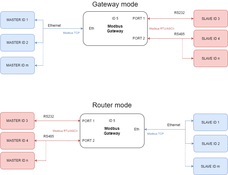
Transmission is carried out by two modes: Gateway and Router. In the Gateway mode the port is used to communicate with Slave devices, but in the Router mode with Master devices. It is also possible to set up different modes on every port. Block diagrams below describe how each of these modes works.
 |
Features
|
Introduction
Devices are based on G01 - G03 gateways (ESP32 Xtensa LX6 microcontroller) and G14 - G16 gateways (STM32F4 microcontroller) depending on needed ports and interfaces.
Dedicated EMC integrated circuits guarantee improved connection quality by limiting the impact of interference typical for an industrial environment.
Specification
|
Redisage PN |
G01 |
G02 |
G03 |
G14 |
G15 |
G16 |
|
|---|---|---|---|---|---|---|---|
|
Ports |
RS232 |
2x |
- |
- |
4x |
2x |
- |
|
RS485 |
- |
1x |
- |
- |
2x |
4x |
|
|
RS232/RS485 |
- |
- |
2x |
- |
- |
- |
|
|
Microcontroller |
ESP32 |
STM32F4 |
|||||
|
WiFi |
N/A |
||||||
|
Power |
Voltage |
12-30 VDC |
|||||
|
Power |
< 1W |
||||||
|
Frame ground connection |
yes |
||||||
|
Baud rate |
up to 115200 bps |
||||||
|
LED indicators |
communication Tx, Rx and power |
||||||
|
RS485 termination |
120 ohm manually enabled |
||||||
|
Connector |
RS232/RS485 |
8 pin terminal block max. 2.5 mm2 wire |
|||||
|
Power |
3 pin terminal block max. 2.5 mm2 wire |
||||||
|
Ethernet |
RJ45 |
||||||
|
Transmission |
RS485 |
max. 1,200 m at 9.6 kbps; max. 400 m at 115.2 kbps |
|||||
|
Mounting and enclosure |
DIN rail, plastic PA - UL 94 V0, black/green |
||||||
|
Temperatures |
-40°C to +75°C operating and storage |
||||||
|
Humidity |
10 - 90% RH, non-condensing |
||||||
|
ESD protection |
±4 kV contact discharge / ±8 kV air discharge |
||||||
|
Certification |
CE, RoHS |
||||||
Applications
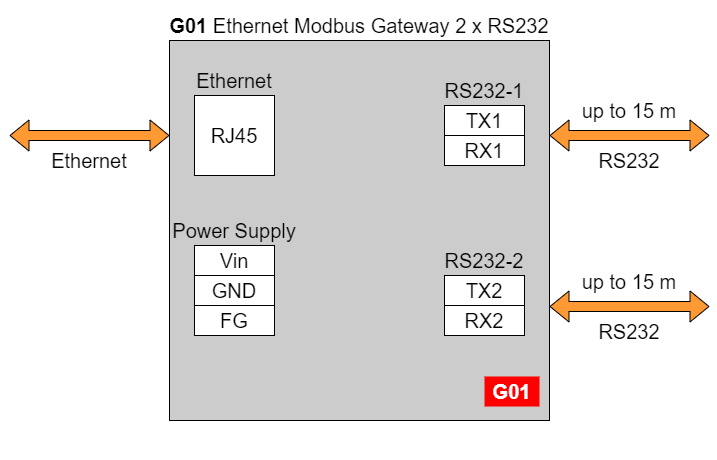
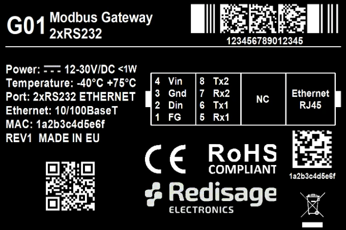
G01 - Ethernet Modbus Gateway 2 x RS232
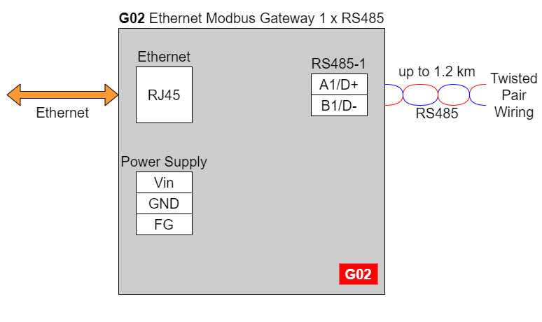
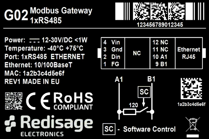
G02 - Ethernet Modbus Gateway 1 x RS485
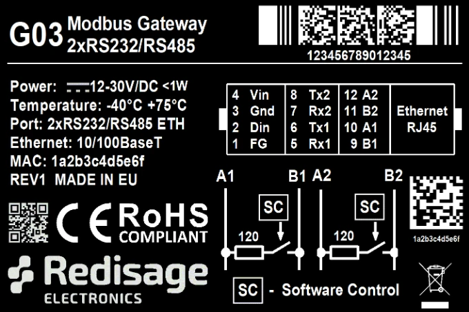
G03 - Ethernet Modbus Gateway 2 x RS232/RS485
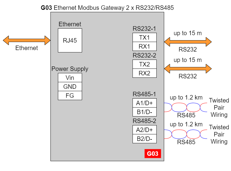
In the G03 gateway user should use only RS232 or only RS485 interface of one port as they occupy the same internal bus of the device.
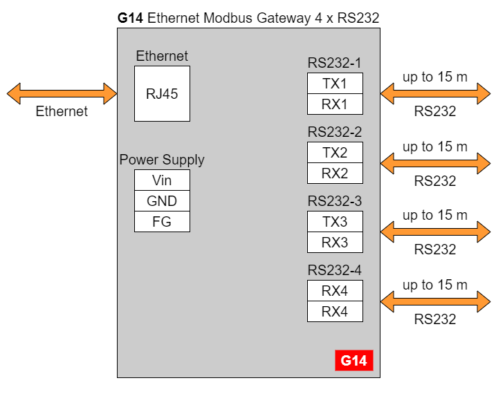
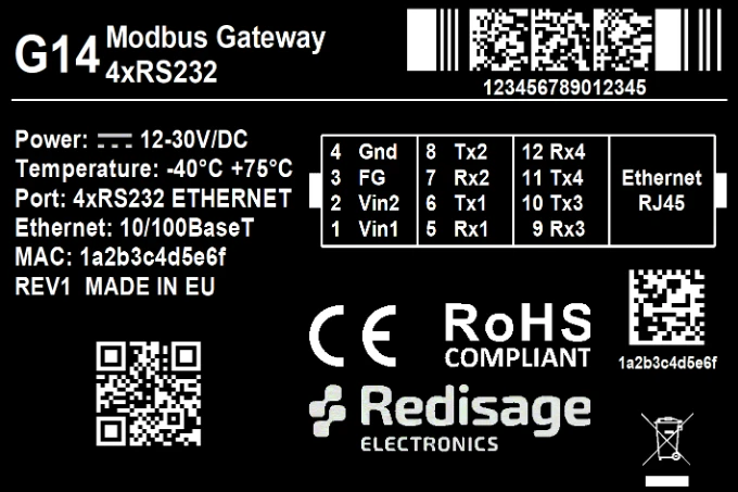
G14 - Ethernet Modbus Gateway 4 x RS232
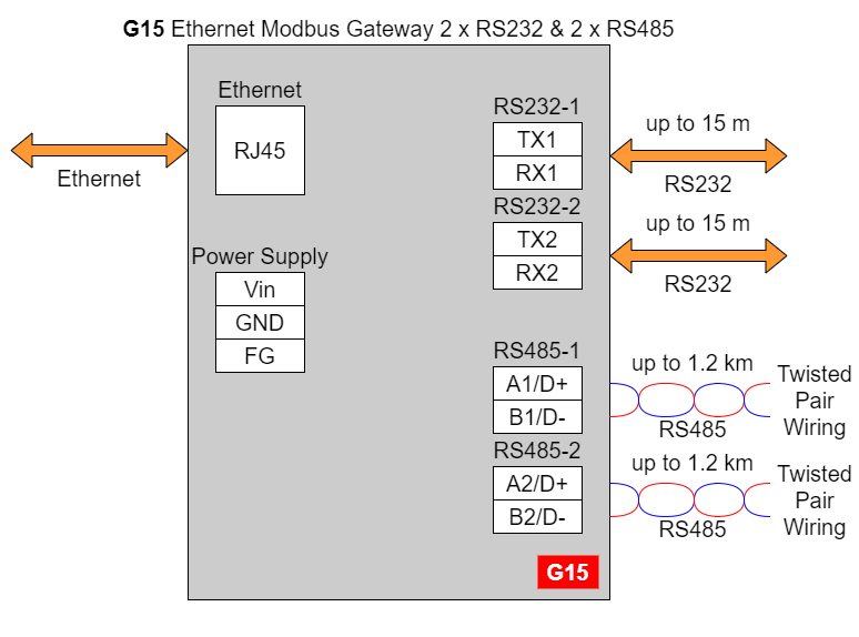
G15 - Ethernet Modbus Gateway 2 x RS232 & 2 x RS485
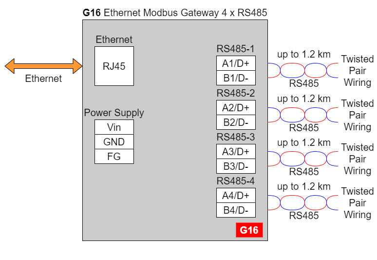
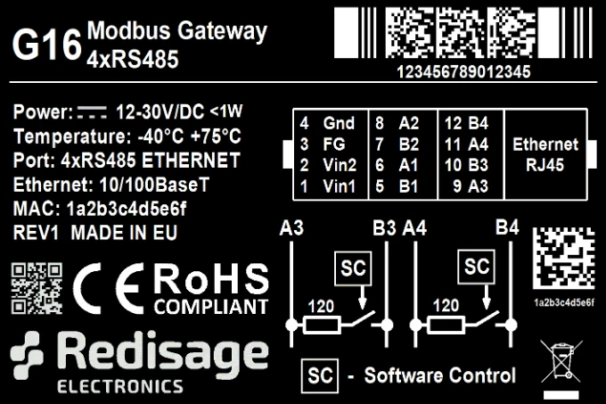
G16 - Ethernet Modbus Gateway 4 x RS485
Frame Ground FG
Electronic circuits are constantly prone to electrostatic discharge ESD.
Redisage Electronics modules feature a design for the frame ground terminal block FG.
The frame ground provides a path for bypassing ESD, which provides enhanced static protection ESD abilities and ensures the module is more reliable.
Connecting FG terminal block to the earth ground will bypass the ESD disturbances outside the device so will provide a better level of protection against ESD.
Frame Ground FG connection reference drawing is provided below.
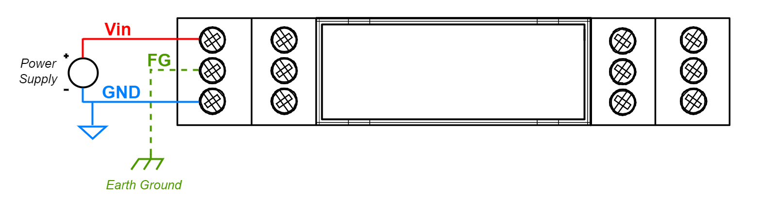
If earth ground is not availabe FG can be left floating or can be connected with power supply GND.
Pin Assignments
|
G01
|
G02
|
G03
|
|
G14
|
G15
|
G16
|

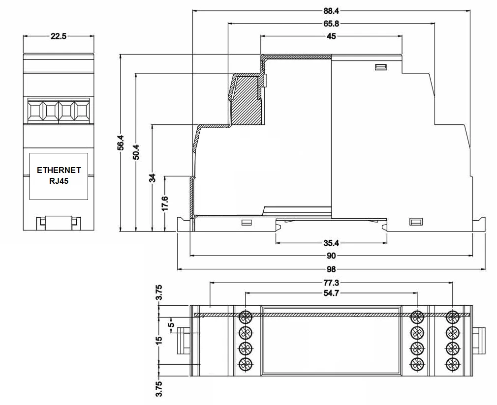
Enclosure Dimensions
U Module Enclosure.
98 x 22.5 x 56.4
Units: mm.
Getting Started
Power Supply
Ethernet Modbus gateways G01 - G03 and G14 - G16 have wide voltage power input 12 - 30 VDC. The power consumption is less than 1 W.
LED Indicators
Ethernet Modbus gateways G01 - G03 have 3 LED indicators:
- PW LED Blue - Power
- ETH LED Green - Network activity
- ST LED Orange - USB-UART Serial console mode

Ethernet Modbus gateways G14 - G16 have 5 LED indicators:
- PW LED Blue - Power
- ER LED Yellow - Error
- ETH LED Green - Network activity
- COM LED Green - RS232/RS485 activity
- CN LED Yellow - Console mode
- SR LED Red - Service mode

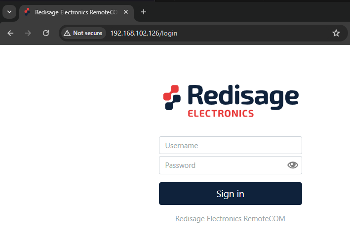
Configuration by the Web Page
Default configuration of the Ethernet Modbus gateways:
- IP address: 192.168.100.100
- Subnet mask: 255.255.255.0
- Gateway: 192.168.100.1
- DNS 1: 192.168.100.1
- DNS 2: 8.8.8.8
Default login details:
- User name: admin
- Password: admin123
To access to the web page open the web browser, type the IP address in the address bar and log in using the default user name and password. The device and a PC must be connected to the same Local Area Network.
After successful login, the “Status” page will show the current status of the ports.
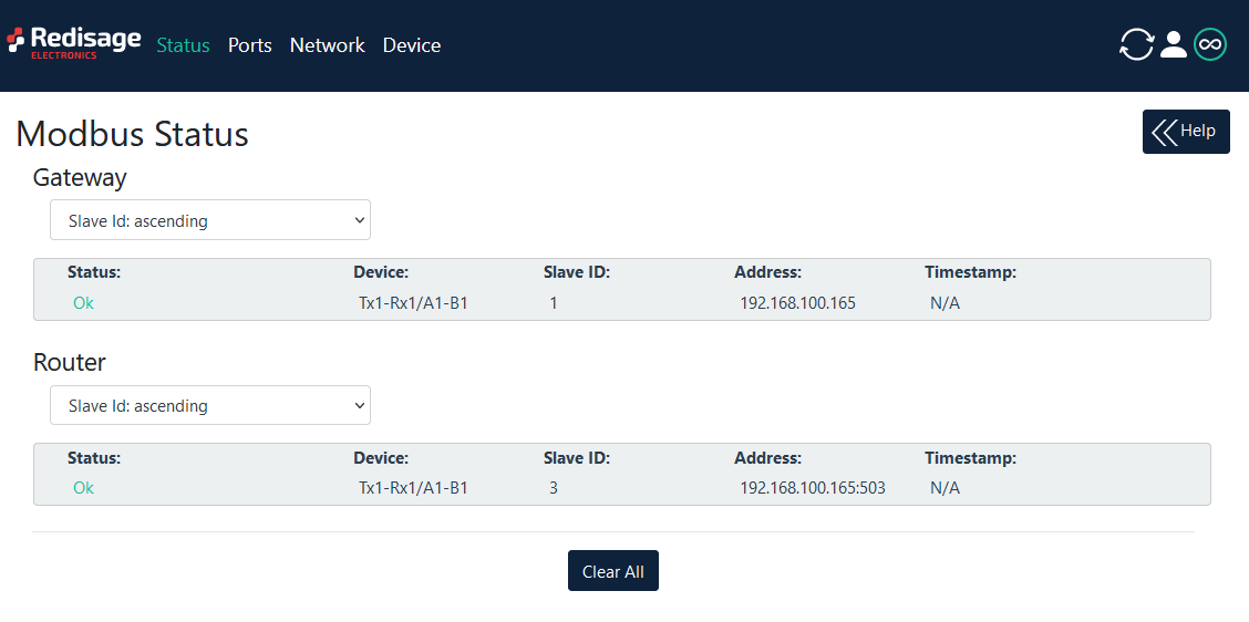
To change the user name and password click on the user icon and select “Edit user”.
Ports configuration is possible on the “Ports” page.
(...)