Data Sheet
{{@178#bkmrk-modbus-gateways-allo}@178}}
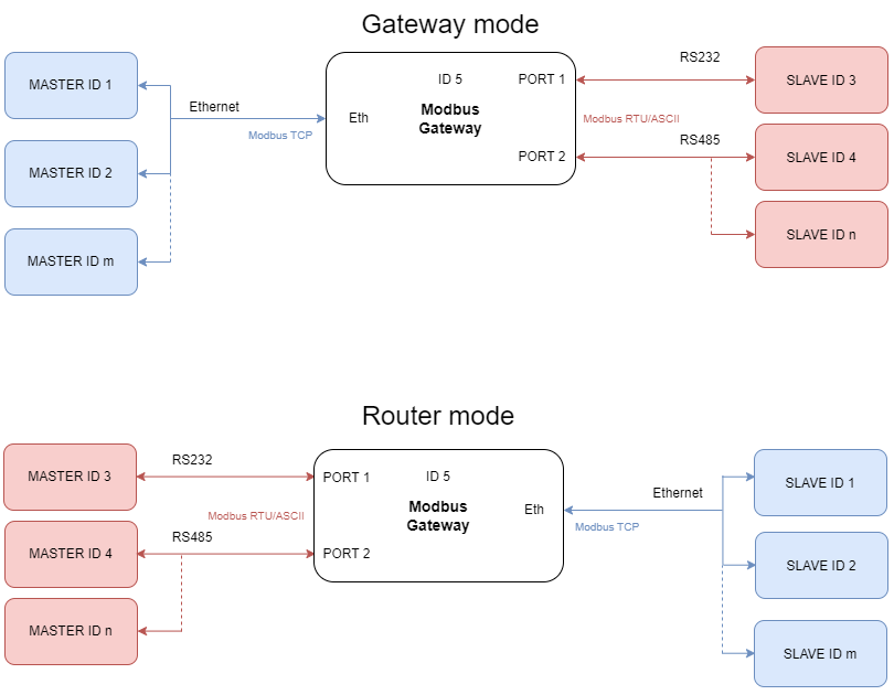
Transmission is carried out by two modes: Gateway and Router. In the Gateway mode the port is used to communicate with Slave devices, but in the Router mode with Master devices. It is also possible to set up different modes on every port. Block diagrams below describe how each of these modes works.
 |
Features
|
Introduction
Devices are based on G01 - G03 gateways (ESP32 Xtensa LX6 microcontroller) and G14 - G16 gateways (STM32F4 microcontroller) depending on needed ports and interfaces.
Dedicated EMC integrated circuits guarantee improved connection quality by limiting the impact of interference typical for an industrial environment.
{{@175#bkmrk-specification}}
{{@175#bkmrk-redisage-pn-g01-g02-}}
Variants
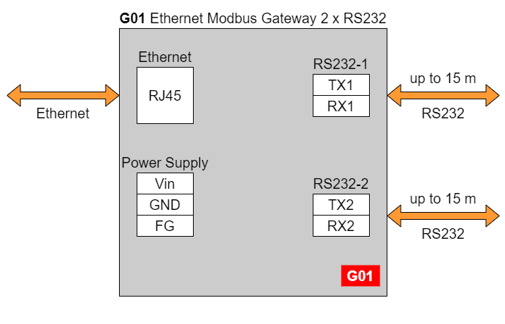
G01 - Ethernet Modbus Gateway 2 x RS232
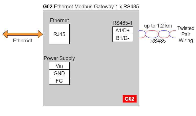
G02 - Ethernet Modbus Gateway 1 x RS485
G03 - Ethernet Modbus Gateway 2 x RS232/RS485
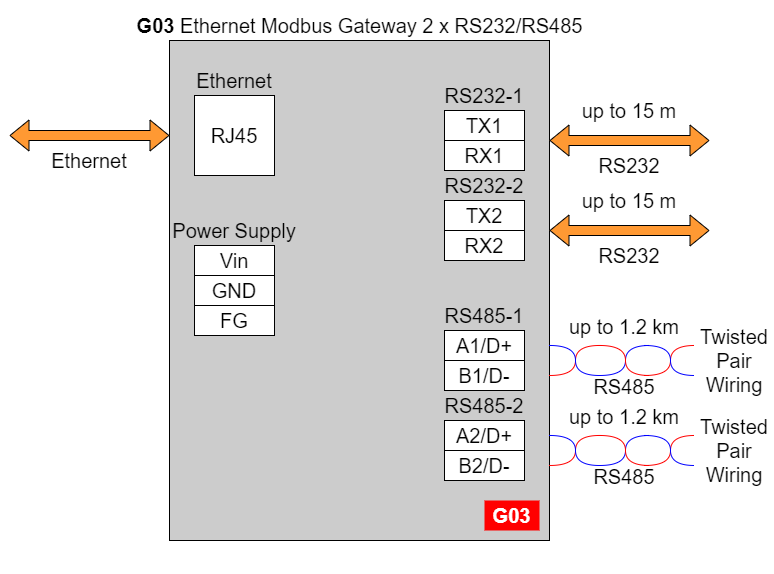
In the G03 gateway user should use only RS232 or only RS485 interface of one port as they occupy the same internal bus of the device.
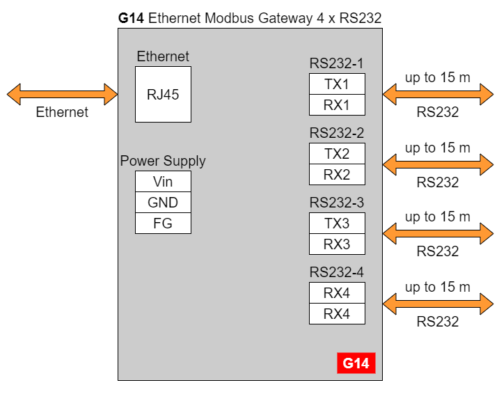
G14 - Ethernet Modbus Gateway 4 x RS232
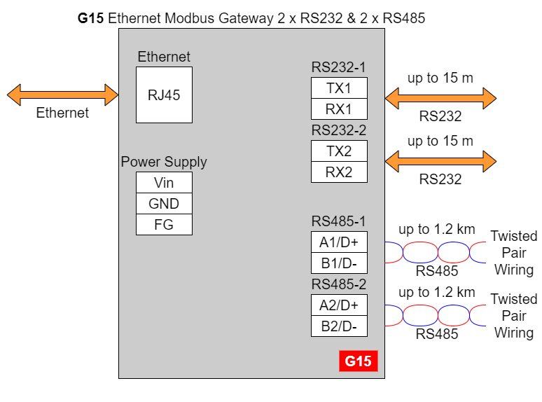
G15 - Ethernet Modbus Gateway 2 x RS232 & 2 x RS485
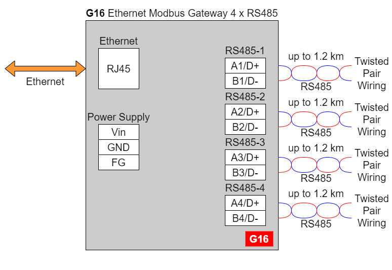
G16 - Ethernet Modbus Gateway 4 x RS485
{{@169}}
{{@175#bkmrk-pin-assignments}}
{{@175#bkmrk-g01-g02-g03-g14-g15-}}
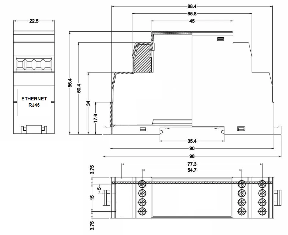
Enclosure dimensions
U Module Enclosure.
98 x 22.5 x 56.4
Units: mm.
Getting started
Power supply
Ethernet Modbus gateways G01 - G03 and G14 - G16 have wide voltage power input (12 - 30 VDC). The power consumption is less than 1 W.
LED indicators
Ethernet Modbus gateways G01 - G03 have 3 LED indicators:
- PW LED Blue - Power
- ETH LED Green - Network activity
- ST LED Orange - USB-UART Serial console mode

Ethernet Modbus gateways G14 - G16 have 5 LED indicators:
- PW LED Blue - Power
- ER LED Yellow - Error
- ETH LED Green - Network activity
- COM LED Green - RS232/RS485 activity
- CN LED Yellow - Console mode
- SR LED Red - Service mode

Configuration by the Web Page
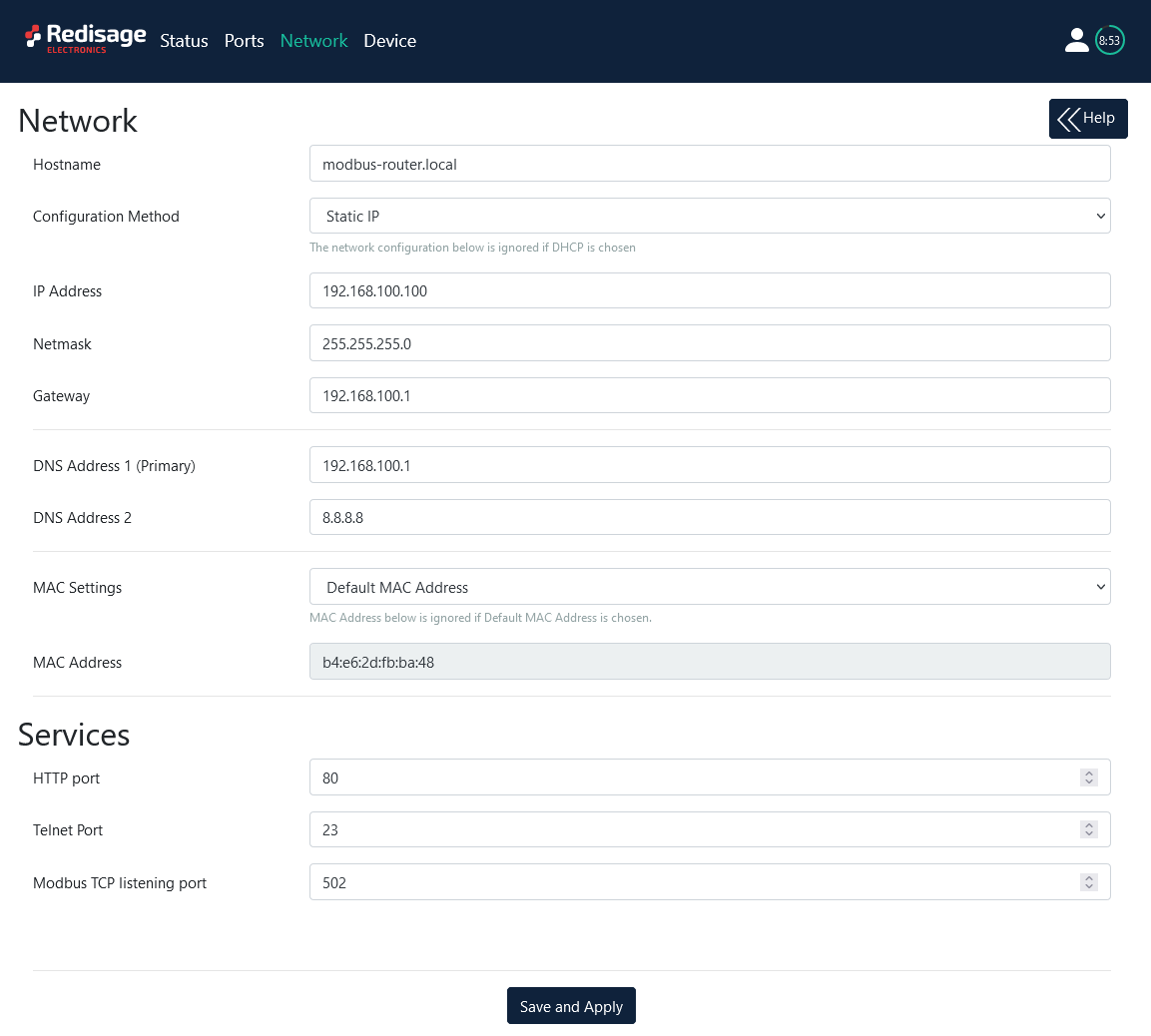
Default configuration of the Ethernet Modbus gateways:
- IP address: 192.168.100.100
- Subnet mask: 255.255.255.0
- Gateway: 192.168.100.1
- DNS 1: 192.168.100.1
- DNS 2: 8.8.8.8
Default login details:
- User name: admin
- Password: admin123
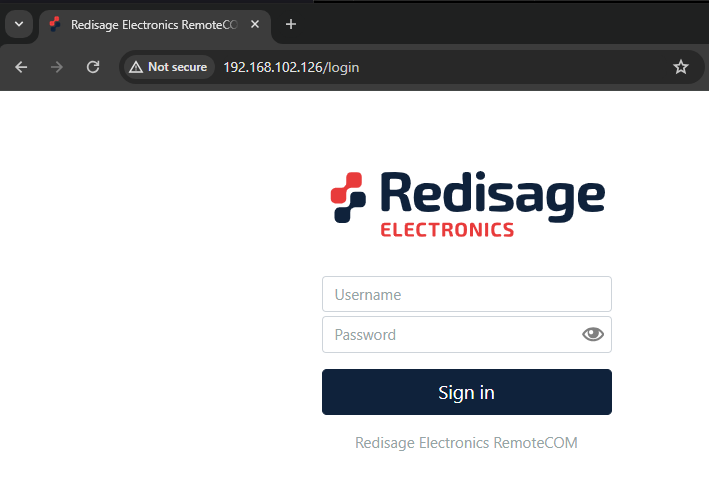
To access to the web page open the web browser, type the IP address in the address bar and log in using the default user name and password. The device and a PC must be connected to the same Local Area Network.
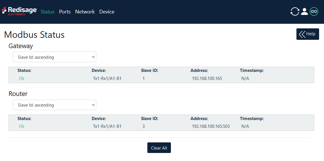
After successful login, the “Status” page will show the current status of the ports.
To change the user name and password click on the user icon and select “Edit user”.
Ports configuration is available on the “Ports” page.

{{@175#bkmrk-item-description-int}}
Changing port’s service closes all sockets connected to the ports.
Changing port’s service closes all sockets connected to the ports.
Network settings can be changed on the “Network” page.
{{@175#bkmrk-item-description-hos}}
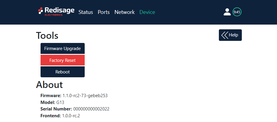
On the “Device” page there are tools used to a firmware update, a factory reset and a device reboot. There is also basic information about the device.
{{@175#bkmrk-item-description-fir}}
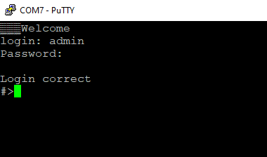
Configuration by the Serial Console
The device has the ability to be reconfigured via a serial console. In case of the G01 - G03 Modbus gateways an additional USB/UART converter is needed.
{{@177#bkmrk-procedure-to-enter-s}}
{{@177#bkmrk-turn-off-the-power-o}}
{{@177#bkmrk-procedure-to-enter-s-1}}
{{@177#bkmrk-install-stm32-virtua}}
Once this is done, log in using the default username and password, then change the network settings using "ipconfig" command.
{{@175#bkmrk-list-of-all-commands}}
{{@175#bkmrk-command-description-}}
{{@176}}
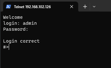
Configuration by the Telnet Console
Access to the Telnet console can be obtained using a serial terminal program. Configure the connection type to Telnet, enter the IP address and Telnet port number (23 by default).
Console commands are the same as ones described in the serial console section.
Reset to Factory Defaults
Reset to factory defaults is possible on the web page in the device section or using the service mode.
Service mode
{{@177#bkmrk-procedure-to-enter-s-2}}
{{@177#bkmrk-turn-off-the-power-o-1}}
{{@177#bkmrk-procedure-to-enter-s-3}}
{{@177#bkmrk-install-stm32-virtua-1}}
{{@175#bkmrk-list-of-commands-in-}}
{{@175#bkmrk-command-description--1}}
{{@175#bkmrk-in-the-service-mode%2C}}
{{@168}}
SR-D