Data Sheet
Modbus gateways allow data transmission between LAN hosts and serial devices by converting Modbus protocols (Modbus TCP and Modbus RTU/ASCII). They are intended to be used in industrial networks especially in the field of Industry 4.0 but not only. Apart from extending the capabilities of industrial devices, they can be also adapted up to user’s requirements and needs.
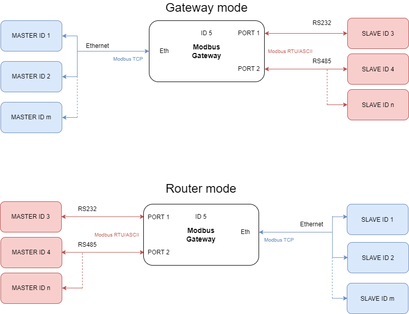
Transmission is carried out by two modes: Gateway and Router. In the Gateway mode the port is used to communicate with Slave devices, but in the Router mode with Master devices. It is also possible to set up different modes on every port. Block diagrams below describe how each of these modes works.
 |
Features
|
Introduction
Devices are based on G01 - G03 gateways (ESP32 Xtensa LX6 microcontroller) and G14 - G16 gateways (STM32F4 microcontroller) depending on needed ports and interfaces.
Dedicated EMC integrated circuits guarantee improved connection quality by limiting the impact of interference typical for an industrial environment.
{{@175#bkmrk-specification}}
{{@175#bkmrk-redisage-pn-g01-g02-}}
Variants
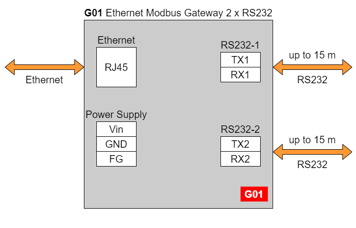
G01 - Ethernet Modbus Gateway 2 x RS232
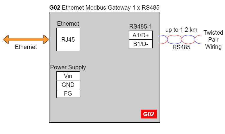
G02 - Ethernet Modbus Gateway 1 x RS485
G03 - Ethernet Modbus Gateway 2 x RS232/RS485
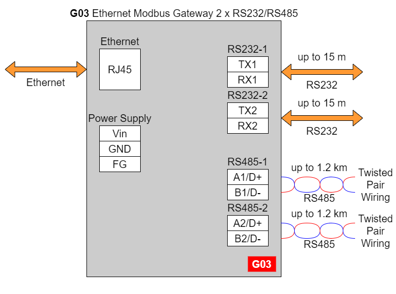
In the G03 gateway user should use only RS232 or only RS485 interface of one port as they occupy the same internal bus of the device.
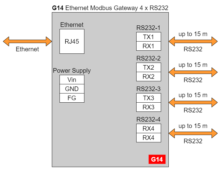
G14 - Ethernet Modbus Gateway 4 x RS232
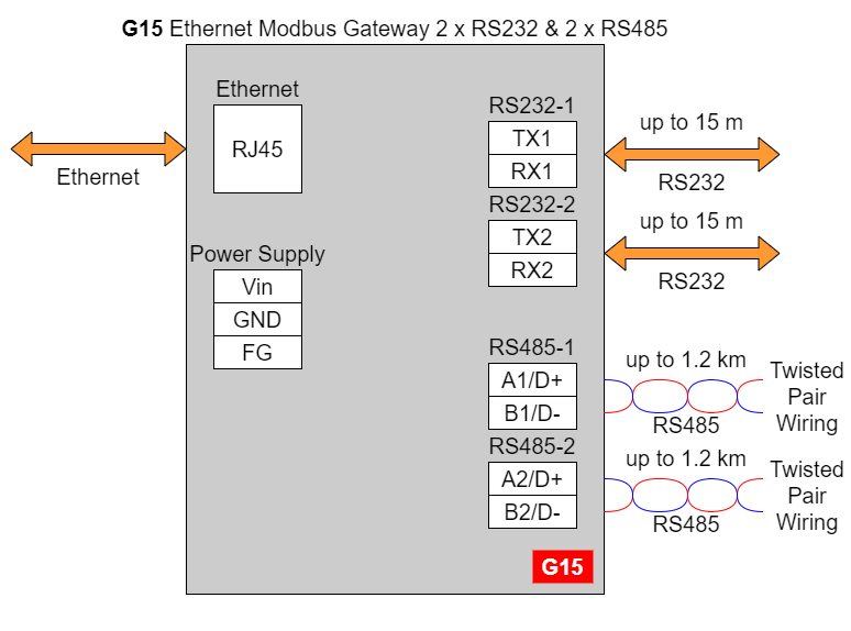
G15 - Ethernet Modbus Gateway 2 x RS232 & 2 x RS485
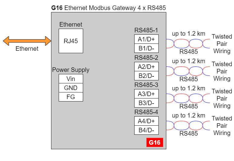
G16 - Ethernet Modbus Gateway 4 x RS485
{{@169#bkmrk-frame-ground-fg}}
{{@169#bkmrk-electronic-circuits-}}
{{@169#bkmrk-frame-ground-fg-conn}}
{{@169#bkmrk-if-earth-ground-is-n}}
{{@175#bkmrk-pin-assignments}}
{{@175#bkmrk-g01-g02-g03-g14-g15-}}
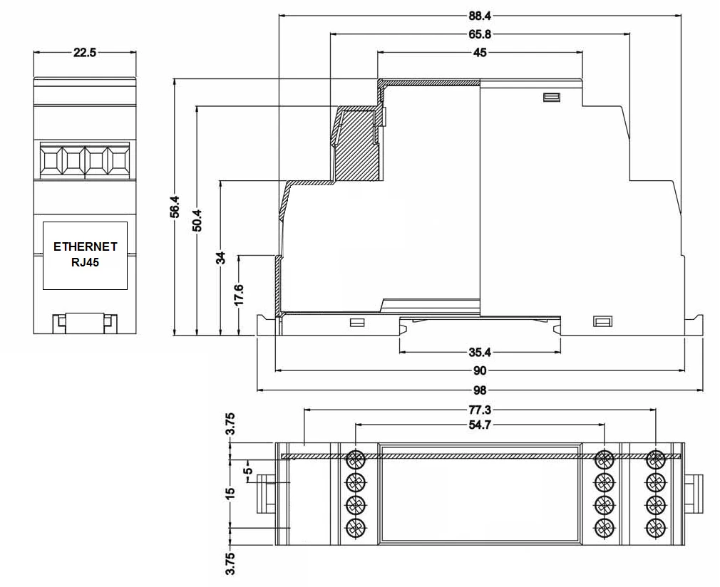
Enclosure dimensions
U Module Enclosure.
98 x 22.5 x 56.4
Units: mm.
Getting started
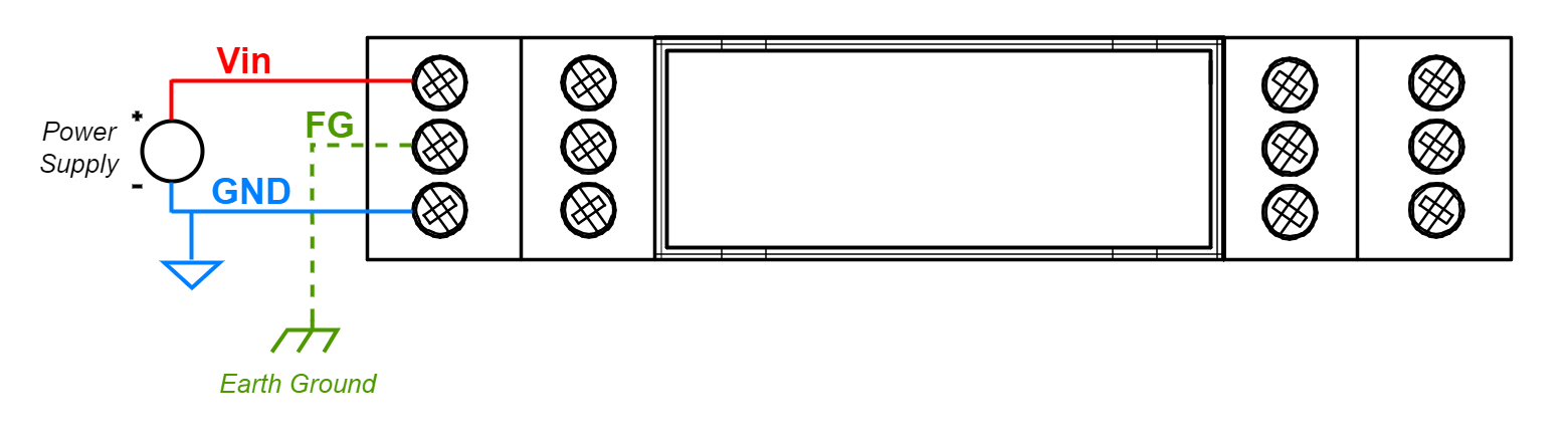
Power supply
Ethernet Modbus gateways G01 - G03 and G14 - G16 have wide voltage power input (12 - 30 VDC). The power consumption is less than 1 W.
LED indicators
Ethernet Modbus gateways G01 - G03 have 3 LED indicators:
- PW LED Blue - Power
- ETH LED Green - Network activity
- ST LED Orange - USB-UART Serial console mode

Ethernet Modbus gateways G14 - G16 have 5 LED indicators:
- PW LED Blue - Power
- ER LED Yellow - Error
- ETH LED Green - Network activity
- COM LED Green - RS232/RS485 activity
- CN LED Yellow - Console mode
- SR LED Red - Service mode

Configuration by the Web Page
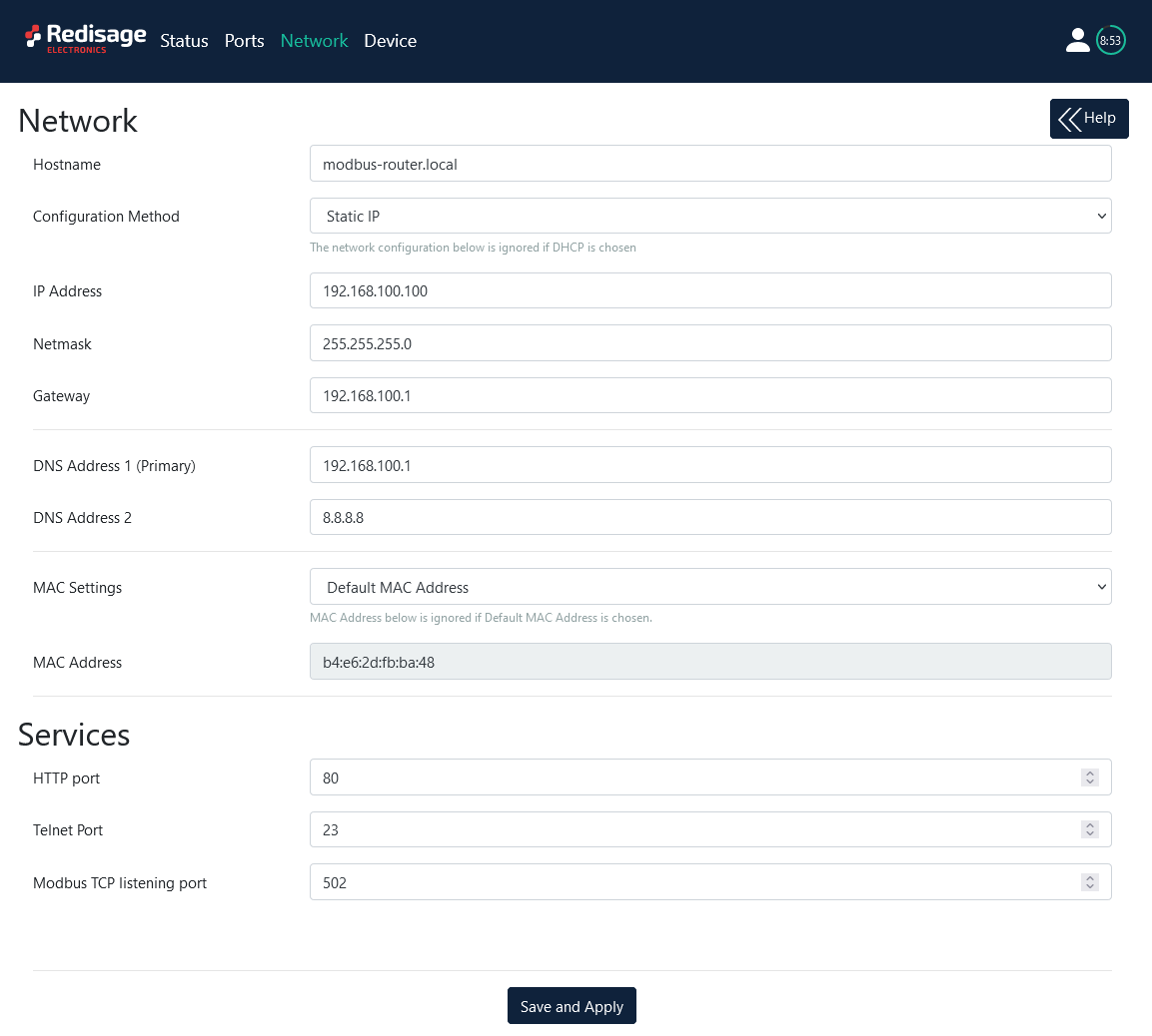
Default configuration of the Ethernet Modbus gateways:
- IP address: 192.168.100.100
- Subnet mask: 255.255.255.0
- Gateway: 192.168.100.1
- DNS 1: 192.168.100.1
- DNS 2: 8.8.8.8
Default login details:
- User name: admin
- Password: admin123
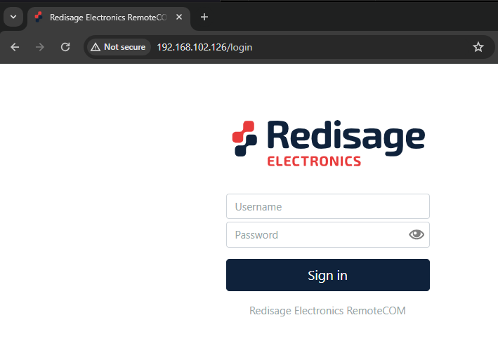
To access to the web page open the web browser, type the IP address in the address bar and log in using the default user name and password. The device and a PC must be connected to the same Local Area Network.
After successful login, the “Status” page will show the current status of the ports.
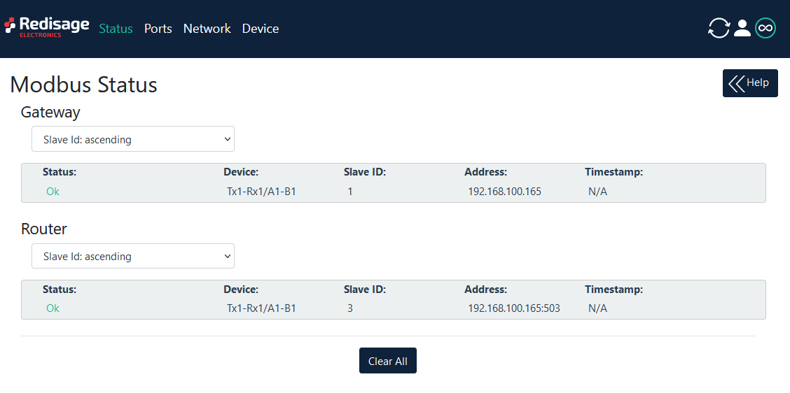
To change the user name and password click on the user icon and select “Edit user”.
Ports configuration is possibleavailable on the “Ports” page.

{{@175#bkmrk-item-description-int}}
Changing port’s service closes all sockets connected to the ports.
Changing port’s service closes all sockets connected to the ports.
Network settings can be changed on the “Network” page.
{{@175#bkmrk-item-description-hos}}
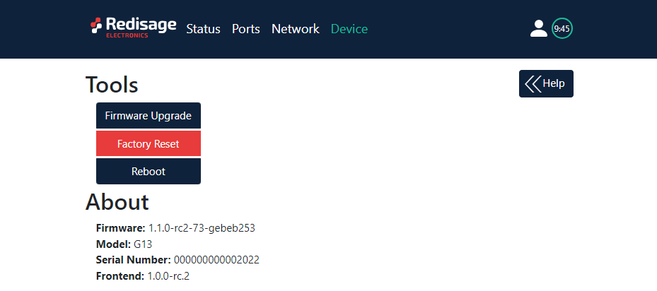
On the “Device” page there are tools used to a firmware update, a factory reset and a device reboot. There is also basic information about the device.
{{@175#bkmrk-item-description-fir}}
Configuration by the Serial Console
The device has the ability to be reconfigured via a serial console. In case of the G01 - G03 Modbus gateways an additional USB/UART converter is needed.
For G01 - G03 gateways
- Turn off the power of the device.
- Connect Ethernet converter to the dedicated USB/UART converter via the microUSB port.
- Connect the USB/UART converter to the PC.
- Open the serial console (default baud rate is 115200 bps).
- Press and hold the S1 button.
- Turn on the power.
- Wait until the ST indicator (orange LED) lights up (it should light up after red light - service mode).
- Release the S1 button.
- Login using user’s personal credentials or default login details.
- If the process is successful, configuration command can be typed into the terminal.
For G14 - G16 gateways
- Install STM32 Virtual COM Port Driver.
- Turn off the power of the device.
- Connect Ethernet converter directly to the PC (the dedicated USB/UART converter is not obligatory).
- Open the serial console (default baud rate is 115200 bps).
- Press and hold the S1 button.
- Turn on the power.
- Wait until the ST indicator (yellow LED) lights up.
- Release the S1 button.
- Login using user’s personal credentials or default login details.
- If the process is successful, configuration command can be typed into the terminal.
Once this is done, log in using the default username and password, then change the network settings using "ipconfig" command.

{{@175#bkmrk-list-of-all-commands}}
{{@175#bkmrk-command-description-}}
{{@176#bkmrk-modbus-ports-configu}}
{{@176#bkmrk-modbus-modbus-helppr}}
- modbus
- modbus help
Print command help. - modbus int_addr VALUE
Set internal Modbus address.
Example:
modbus int_addr 5 - modbus idlet VALUE
Show or set the idle TIME (in seconds) of the TCP connection after which the TCP connection is terminated by the converter and the TCP socket is released.
Example:
modbus idlet 720
If a subcommand that normally sets a value is not given an argument, it will print the current value.
Example:
modbus idlet
Set idle time is 5000
- modbus help
- modbus_ports
- modbus_ports help
Print command help, does not require com_number. - modbus_ports PORT_NUMBER add_slaves [SLAVE_ADDR ;/- SLAVE_ADDR, *]
Set all addresses of slaves connected to com_port. A star in value means fill rest free slaves. It means all slaves that are not set to other ports will be set to this one.
Example:
modbus_ports 1 addslaves 124
Example:
modbus_ports 1 addslaves 12-124
Example:
modbus_ports 1 addslaves 12;14;18
Example:
modbus_ports 1 addslaves 12;14-17;150-200
Example:
modbus_ports 1 addslaves 12;14-17;150-200, * - modbus_ports PORT_NUMBER show_slaves
Show addresses of slaves connected to com_port.
Example:
modbus_ports 1 showslaves - modbus_ports PORT_NUMBER mode [ascii/rtu]
Set Modbus port mode to ASCII or RTU.
Example:
modbus_ports 2 mode ascii - modbus_ports PORT_NUMBER baud [RATE]
Set the baud rate to RATE. For a list of acceptable baud rates, please refer to the manual.
Example:
modbus_ports 1 baud 9600 - modbus_ports PORT_NUMBER bits [CPS]
Set bit count to C, parity to P, and stop bits to S. Valid values are:
C: 7, 8 or 9
P: N, E or O (N- none, E- even, O- odd)
S: 1 or 2
Example:
modbus_ports 1 bits 8N1
Example:
modbus_ports 2 bits 7O1 - modbus_ports PORT_NUMBER state [GATEWAY/ROUTER/DISABLE]
Enable or disable uart functionality.
Example:
modbus_ports 1 state GATEWAY
Example:
modbus_ports 2 state DISABLE - modbus_ports PORT_NUMBER termination [on/off]
Enable or disable termination on RS485 port.
Example:
modbus_ports 1 termination on - modbus_ports PORT_NUMBER slave_response_timeout TIMEOUT
Set response timeout (serial slave) in ms. When this timeout expires, delayed frames are dropped.
Example:
modbus_ports 1 slave_response_timeout 2000
If a subcommand that normally sets a value is not given an argument, it will print the current value.
Example:
modbus_ports 2 baud
Set baud rate is 115200
- modbus_ports help
PORT_NUMBER is a number of ports in modbus gateway and it is counted from 0.
- modbus_routing
- modbus_routing help
Print routing's help. - modbus_routing show
Display all active routing table in system.
[LP]: [SLAVES NUMBERS] [IP/HOSTNAME] [PORT] [TIMEOUT] - modbus_routing add SLAVE_ADDR HOSTNAME PORT TIMEOUT
SLAVE_ADDR with HOSTNAME PORT is used by uarts working in Modbus router mode. TIMEOUT (in ms) is used to close the connection if a slave is not responding. The maximum records is 8. One record for one address/ip.
Example:
modbus_routing add 18 192.168.0.10 502 2000
Example:
modbus_routing add 18;25 192.168.0.10 502 2000
Example:
modbus_routing add 18-25 192.168.0.10 502 2000
Example:
modbus_routing add 18-25;* 192.168.0.10 502 2000
Example:
modbus_routing add 18-25 modbus.local 502 2000 - modbus_routing remove [HOSTNAME_NUMBER/all]
Remove Modbus Routing Table record. HOSTNAME_NUMBER is line number from /show/ command.
Example:
modbus_routing remove 2
Example:
modbus_routing remove all
- modbus_routing help
Network settings
The following commands might be helpful to change network settings according to target LAN parameters,
- ipconfig
- ipconfig addr ADDRESS
Set IP address to ADDRESS.
Example:
ipconfig addr 192.168.0.10 - ipconfig mask NETMASK
Set subnet mask to NETMASK (in dot-decimal format).
Example:
ipconfig mask 255.255.255.0 - ipconfig mask BIT_COUNT
Set subnet mask to BIT_COUNT bits.
Example:
ipconfig mask 24 - ipconfig gateway GATEWAY_IP
Set network gateway to GATEWAY_IP.
Example:
ipconfig gateway 192.168.0.1 - ipconfig dhcp [enable/disable]
Enable or disable DHCP client.
Example:
ipconfig dhcp enable - ipconfig dns1 ADDRESS
Set primary DNS to ADDRESS, disable getting DNS from DHCP if enabled.
Example:
ipconfig dns1 192.168.100.1 - ipconfig dns2 ADDRESS
Set secondary DNS to ADDRESS, disable getting DNS from DHCP if enabled.
Example:
ipconfig dns2 1.1.1.1
- ipconfig addr ADDRESS
- eth_mac
- eth_mac help
Print the help message. - eth_mac default
Set device’s MAC address to factory-default one. - eth_mac set MAC_ADDR
Set device’s MAC address to MAC_ADDR. Accepts both dash and colon-separated formats.
Example:
eth_mac set 01-02-03-04-05-06
Example:
eth_mac set 01:02:03:04:05:06
- eth_mac help
- http_port
- http_port help
Print the help message. - http_port PORT_NUMBER
Set http port to PORT_NUMBER. A PORT_NUMBER value must be in range: 1-65535.
Example:
http_port 80 - http_port status
Print current http port.
Example:
http_port status
A current http port is 80
- http_port help
- telnet_port
- telnet_port help
Print the help message. - telnet_port PORT_NUMBER
Set Telnet port to PORT_NUMBER. A PORT_NUMBER value must be in range: 1-65535.
Example:
telnet_port 23 - telnet_port status
Print current Telnet port.
Example:
telnet_port status
A current telnet port is 23
- telnet_port help
- modbus_tcp_port
- modbus_tcp_port help
Print the help message. - modbus_tcp_port PORT_NUMBER
Set http port to PORT_NUMBER. A PORT_NUMBER value must be in range: 1-65535.
Example:
modbus_tcp_port 502 - modbus_tcp_port status
Print current Modbus port.
Example:
modbus_tcp_port status
A current modbus port is 502
- modbus_tcp_port help
Changing username or password
To change username or password, use user command.
Available commands:
- user help
Print the help message. - user mod_name USER_NAME NEW_NAME
Change the user name to NEW_NAME. It fails if the name is used by another user.
Example:
user mod_name admin NEW_NAME - user passwd USER_NAME
Change USER_NAME's password.
Example:
user passwd admin
****** <- here is entered password, but '*' appears instead
Note: Everyone can change the password for themselves.
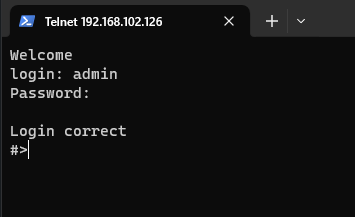
Configuration by the Telnet Console
Access to the Telnet console can be obtained using a serial terminal program. Configure the connection type to Telnet, enter the IP address and Telnet port number (23 by default).
Console commands are the same as ones described in the serial console section.
Reset to Factory Defaults
Reset to factory defaults is possible on the web page in the device section or using the service mode.
Service mode
Procedure to enter service mode for G01 - G03 gateways
- Turn off the power of the device.
- Connect Ethernet converter to the dedicated USB/UART converter via the microUSB port.
- Connect the USB/UART converter to the PC.
- Open the serial console (default baud rate is 115200 bps).
- Press and hold the S1 button.
- Turn on the power.
- Wait until the ST indicator (red LED) lights up.
- Release the S1 button.
- If the process is successful, service commands can be typed into the terminal.
Procedure to enter service mode for G14 - G16 gateways
- Install STM32 Virtual COM Port Driver (if it was not done before).
- Turn off the power of the device.
- Connect Ethernet converter directly to the PC (the dedicated USB/UART converter is not obligatory).
- Open the serial console (default baud rate is 115200 bps).
- Press and hold the S1 button.
- Turn on the power.
- Wait until the ST indicator (red LED) lights up.
- Release the S1 button.
- If the process is successful, service commands can be typed into the terminal.
{{@175#bkmrk-list-of-commands-in-}}
{{@175#bkmrk-command-description--1}}
{{@175#bkmrk-in-the-service-mode%2C}}
{{@168#bkmrk-additional-notes}}
{{@168#bkmrk-products-family-samp}}

{{@168#bkmrk-https%3A%2F%2Fredisage.com}}
{{@168#bkmrk-disclamer-notesall-p}}