Configuration by the Web Page
This page presents capabilities of the Ethernet Converters configuration. First of all, make sure that converter is connected to power supply and to the LAN using a patch cord. If the device has no static IP set up, it will be necessary to obtain its IP address in the local network. User interface is mostly similar for all gateways but some subpages might be different for several models depending on amount of interfaces. In order to avoid issues, click on a “Help” button in the top right corner on every page.
Login
To access the web page open the browser, type device’s IP address of the converter (default is 192.168.100.100). Then log in using user’s personal credentials. If it is a first configuration or the converter had a factory reset, use default login details (login: admin, password: admin123).
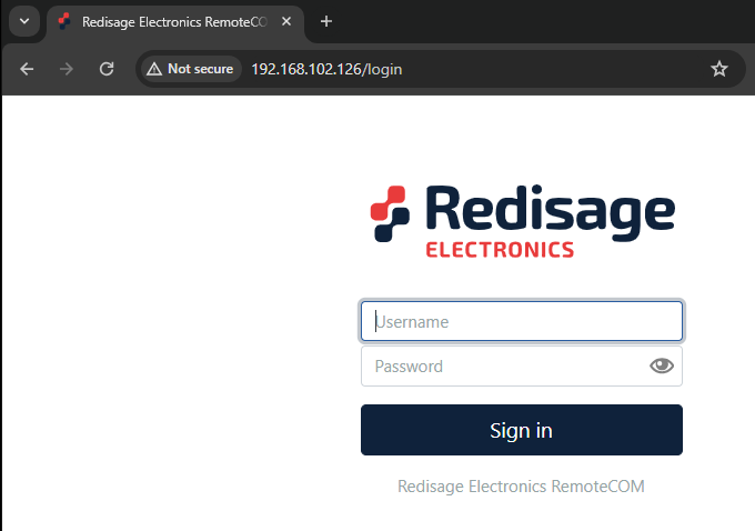
The configuration is available only if devices are connected to the same Local Area Network as the computer used for it.
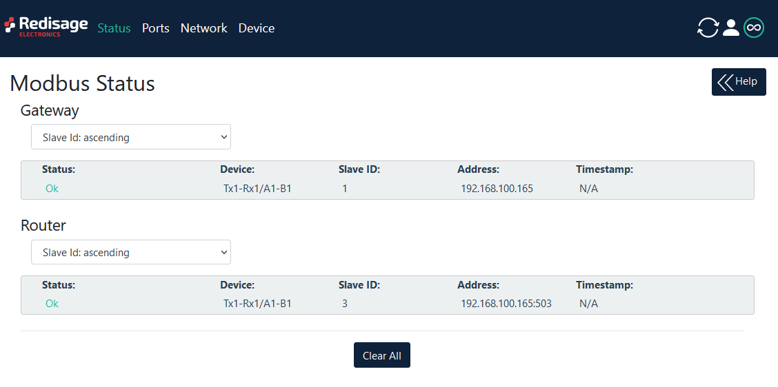
Status page
After a successful login, there should be an insight to a list of available connections. If there is more than one connection, it is possible to sort them by ID, timestamp or status.
Changing username or password
After clicking “Edit User” under the user icon, it is possible to change the username or the password.
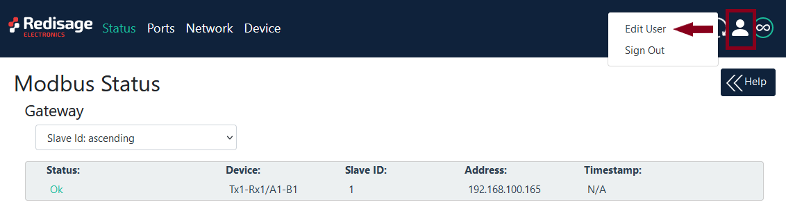
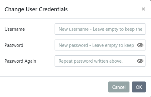
If login details were forgotten, it would be necessary to do a factory reset via a USB/UART converter and a serial console.
Ports configuration

|
Item |
Description |
|
|
Internal Modbus Address |
Internal Modbus Address is qualified by the Gateway/Router as a request for internal resources. The Internal Modbus Address has a higher priority than the Gateway Slave Address. |
|
|
Idle Time [s] |
Determine a time thread waits for the TCP connection. If time expired, the connection and thread are closed. Used only in Gateway Mode. |
|
|
UART Mode |
Gateway |
Define the port's role in the system. In the Gateway Mode the port is used to communicate with Modbus Slave. |
|
Router |
Define the port's role in the system. In the Router Mode the port is used to communicate with Modbus Master. Note the Routing Configuration section below if the Router Mode is chosen. |
|
|
Disabled |
Disable the port. |
|
|
UART Protocol |
Determine a protocol used for a communication. |
|
|
Gateway Slaves |
Addresses of Modbus Slave Devices connected to Gateway UART ports. Multiple addresses can be written in one field, e.g. 9;11;14-17;80. This field is available only in the Gateway Mode. Use * to select all not assigned addresses. |
|
|
Slaves Response Timeout [ms] |
Specify how long the device will wait for response from Modbus Slave. |
|
|
Baud Rate |
Determine the port's transmission speed over the data channel. |
|
|
Data Bits |
Determine the number of data bits in the port's message frame. |
|
|
Parity |
Enable/disable the parity check in the port's message frame. |
|
|
Stop Bits |
Determine the number of stop bits in the port's message frame. |
|
|
Termination |
Enable/disable termination on RS line. |
|
|
Routing Slaves |
Addresses of Modbus Slaves connected to Modbus Router. Multiple addresses can be written in one field, e.g. 9;11;14-17;80. Use * to select all not assigned addresses. |
|
|
Slaves Response Timeout [ms] |
Specify how long the device will wait for response from Modbus Slave. |
|
|
IP/Hostname |
Determine IP address or Hostname of Modbus Slave. |
|
|
TCP Port |
Determine TCP port of Modbus Slave. |
|
Make sure to save all the changes with “Save and Apply” button located on the bottom of the page.
In the UDP mode, port number 15051 is reserved for UDP broadcast service.
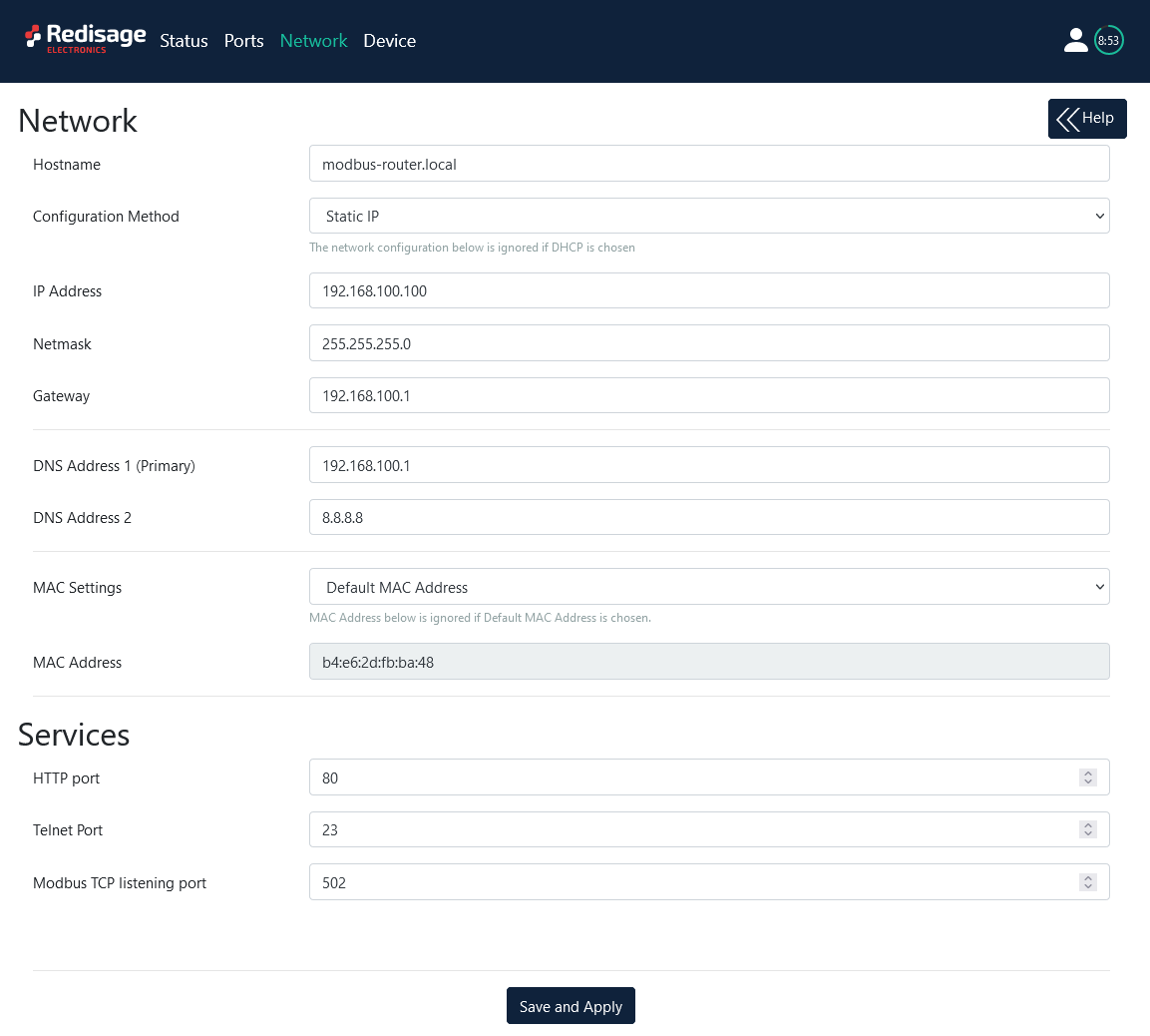
Network settings
In this section, network settings can be changed according to target LAN parameters.
|
Item |
Description |
|
Hostname |
Label that is assigned to the device. |
|
Configuration Method |
Enable/disable the DHCP server. If the DHCP server is disabled, the IP address of the device has to be set manually. |
|
IP Address |
IP address of the device. |
|
Netmask |
Netmask associated with the IP address. |
|
Gateway |
Gateway address currently used by the device. |
|
DNS Address |
Domain Name System used by the device. |
|
MAC Settings |
Allow setting the default MAC address or typing it manually. |
|
MAC Address |
Allow changing the physical address of the device. |
|
HTTP Port |
Determine the port of the control panel. |
|
Telnet Port |
Allow connection with the device via Telnet. |
|
Modbus TCP Listening Port |
Used as an entry point for new Modbus TCP connections. |
It is possible to obtain dynamic IP address. Just switch configuration method from static IP to DHCP (automatic). This process may cause some issues with identifying converters in LAN unless there is an access to the device which is responsible for allocating IP addresses.
Keep in mind that in case of changed IP address user needs to type new IP in the address bar and log in again.
Make sure to save all the changes with “Save and Apply” button located on the bottom of the page.
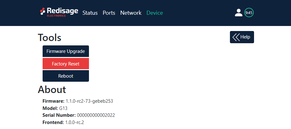
Device page
On the device page there are tools used to a firmware update, a factory reset and a device reboot. There are also some information about the device.
|
Item |
Description |
|
Firmware Update |
Update firmware. |
|
Factory Reset |
Restore default ports settings and default network configuration. |
|
Reboot |
Reboot the device. |
|
About |
Basic information about the device. |
Firmware update
The device firmware update must not be interrupted. Update the device only if experiencing issues, being instructed to do so by our support or requiring the latest features/bugfixes. Failure during the update may 'brick' the device and make it unusable.
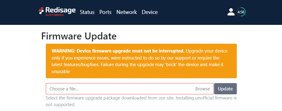
Use the modbus-gateway-mcu-esp32.fir file for a firmware update.
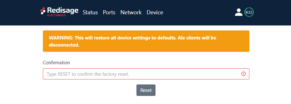
Factory reset
To restore default settings, press the red button. After that, user will be asked to type “RESET”. Then it will take a few seconds to reload the web page and restart the device.