Hardware
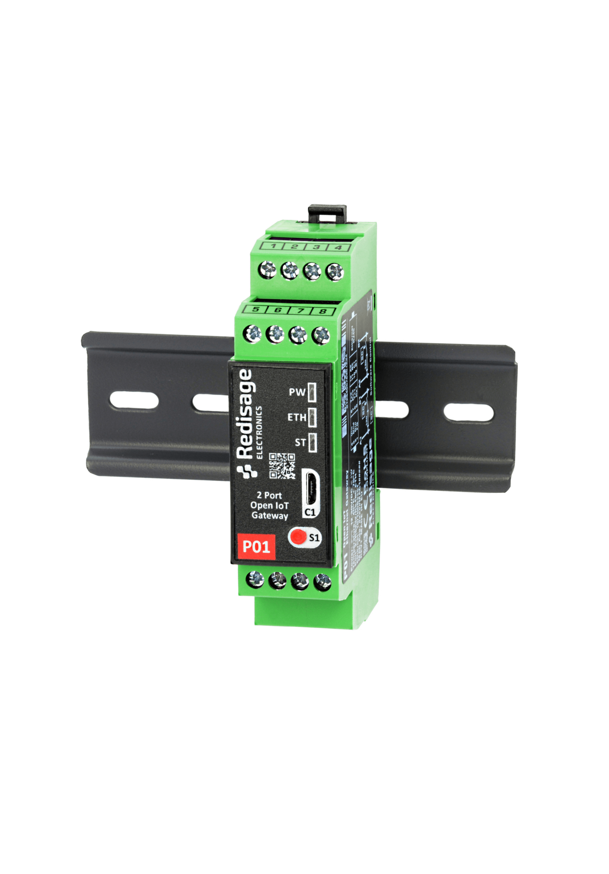
ESP32 Open IoT and IIoT Gateways (P01 & P02)
Features
|
Features |
 |
|---|---|
|
Open IoT gateway |
|
|
ESD protection for the RS485 data line |
|
|
Power supply: +12 to +30 VDC |
|
|
Transmission speed up to 115200 bps |
|
|
Tx, Rx and power LED indicators |
|
|
RS485 embedded termination 120 ohm |
|
|
Optional WiFi |
|
|
Operating temperatures: -40°C to +75°C |
|
|
DIN-rail mounting |
|
|
Dimensions: 90x56.4x22.5 mm |
|
|
3 years warranty |
|
|
Customization of OEM is welcomed |
Frame ground FG
Electronic circuits are constantly prone to electrostatic discharge ESD. Redisage Electronics modules feature a design for the frame ground terminal block FG. The frame ground provides a path for bypassing ESD, which provides enhanced static protection ESD abilities and ensures the module is more reliable. Connecting FG terminal block to the earth ground will bypass the ESD disturbances outside the device so will provide a better level of protection against ESD.
Frame Ground FG connection reference drawing is provided below.
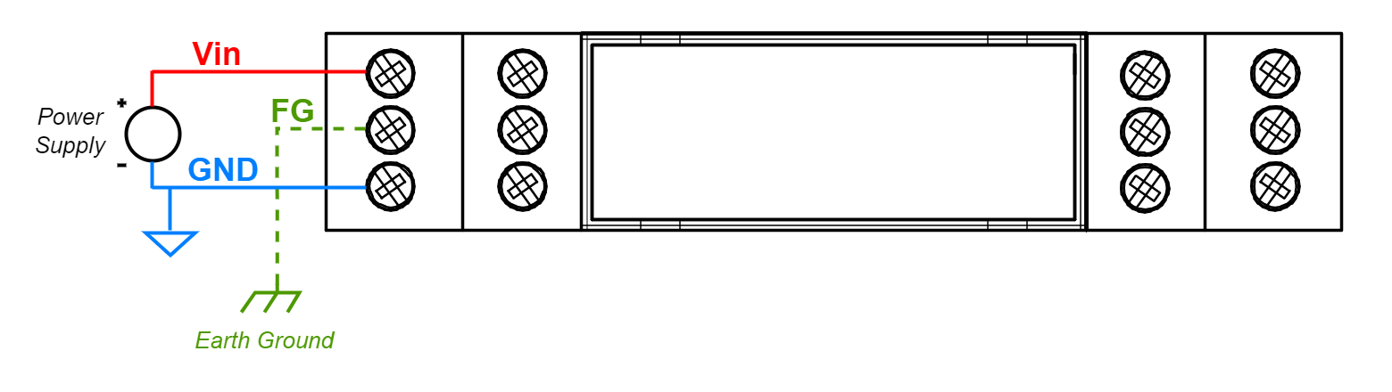
If earth ground is not available FG can be left floating or it can be connected with the power supply GND.
Specifications
|
Redisage PN |
P01 |
P02 |
|
|
Ports |
RS232 |
- |
- |
|
RS485 |
- |
- |
|
|
RS232/RS485 |
2x |
2x |
|
|
Microcontroller |
ESP32 |
||
|
Wi-Fi® |
N/A |
802.11 b/g/n 150 Mbps / 2.4 GHz |
|
|
SMA socket connector for 2.4G antenna |
|
|
|
|
Tactile switch |
|
|
|
|
Power |
Voltage |
12-30 VDC |
|
|
Power |
< 1 W |
||
|
Frame ground protection |
yes |
||
|
Baud rate |
up to 115200 bps |
||
|
LED indicators |
power, link activity, programmable RGB |
||
|
RS485 termination |
120 ohm manually enabled |
||
|
Connector |
RS232/RS485 |
8-pin terminal block max. 2.5 mm2 wire |
|
|
Power |
3-pin terminal block max. 2.5 mm2 wire |
||
|
Ethernet |
RJ45 |
||
|
Transmission |
RS485 |
max. 1,200 m at 9.6 kbps; max. 400 m at 115.2 kbps |
|
|
RS232 |
max. 15 m at 115.2 kbps |
||
|
Mounting and enclosure |
DIN rail, plastic PA - UL 94 V0, black/green |
||
|
Temperatures |
-40°C to +75°C operating and storage |
||
|
Humidity |
10 - 90% RH, non-condensing |
||
|
ESD protection |
±4 kV contact discharge / ±8 kV air discharge |
||
|
Certification |
CE, RoHS, EMC, LVD |
||
|
Norms |
61000-6-2 - Immunity standard for industrial environments 61000-6-4 - Emission standard for industrial environments |
||
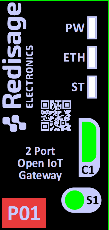
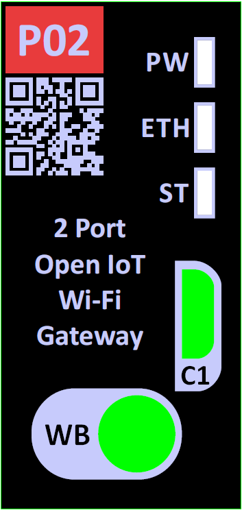
LED indicators
| Gateway P01 |
Gateway P02 |
||||
 |
 |
||||
| LED indicator | Color | Function | LED indicator | Color | Function |
| PW | Blue | Power | PW | Blue | Power |
| ETH | Green | Network activity | ETH | Green | Network activity |
| ST | Red / Green / Blue | Programmable LED | ST | Red / Green / Blue | Programmable LED |
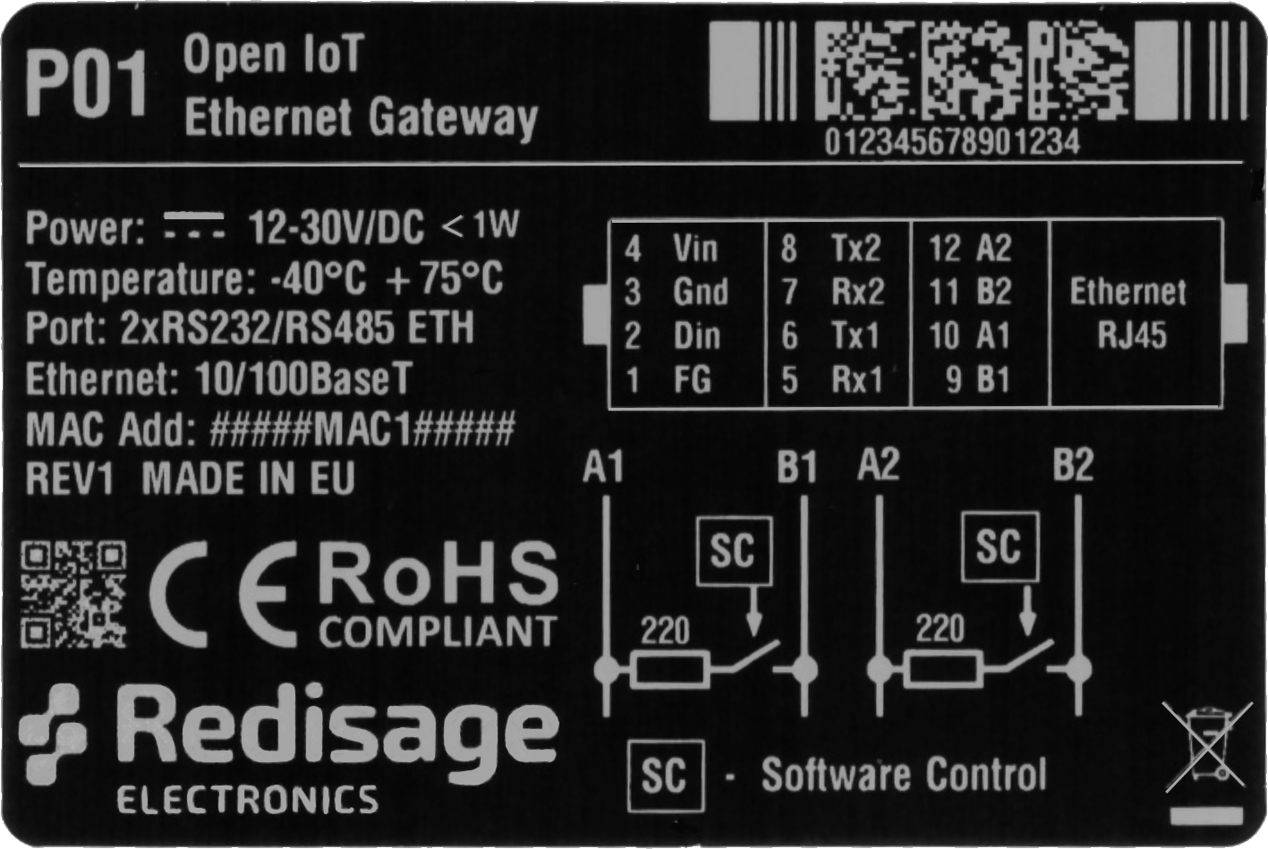
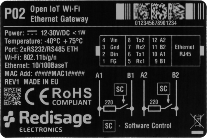
Pin assignments
|
P01
|
P02
|
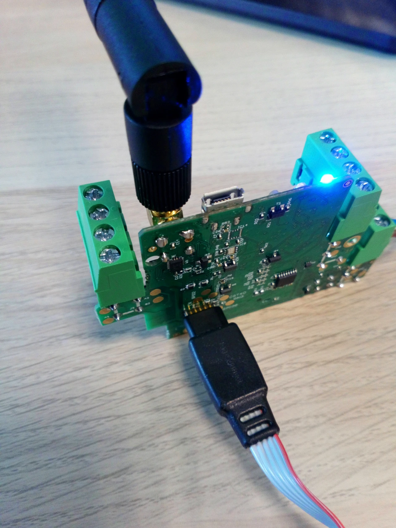
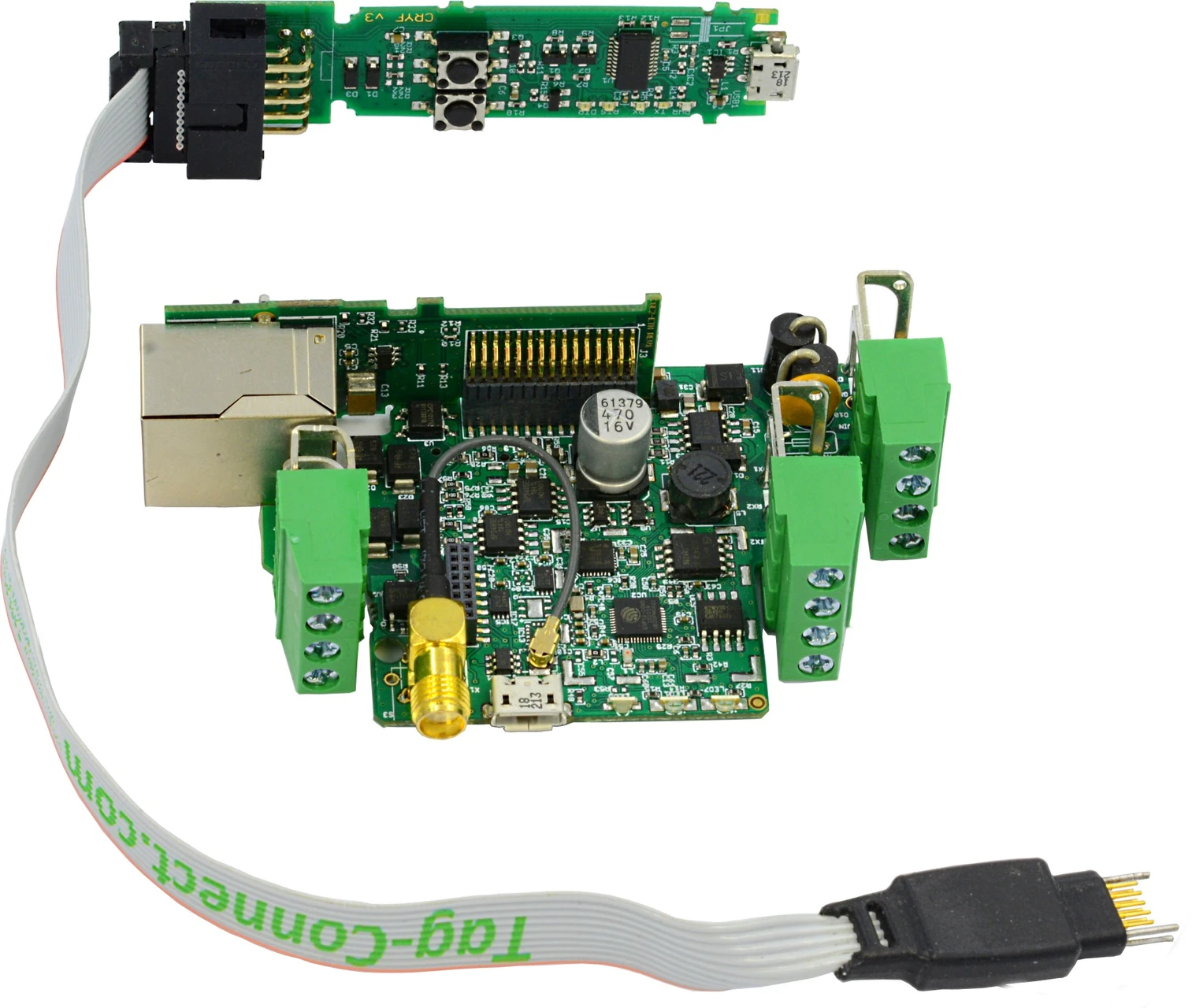
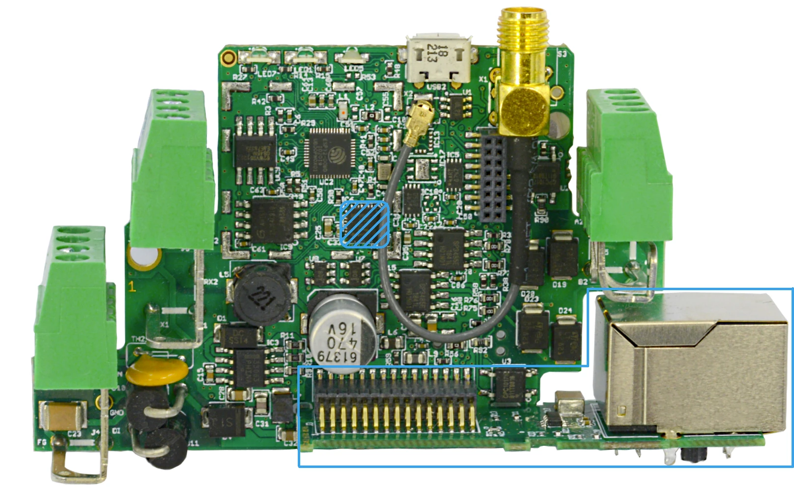
Board overview
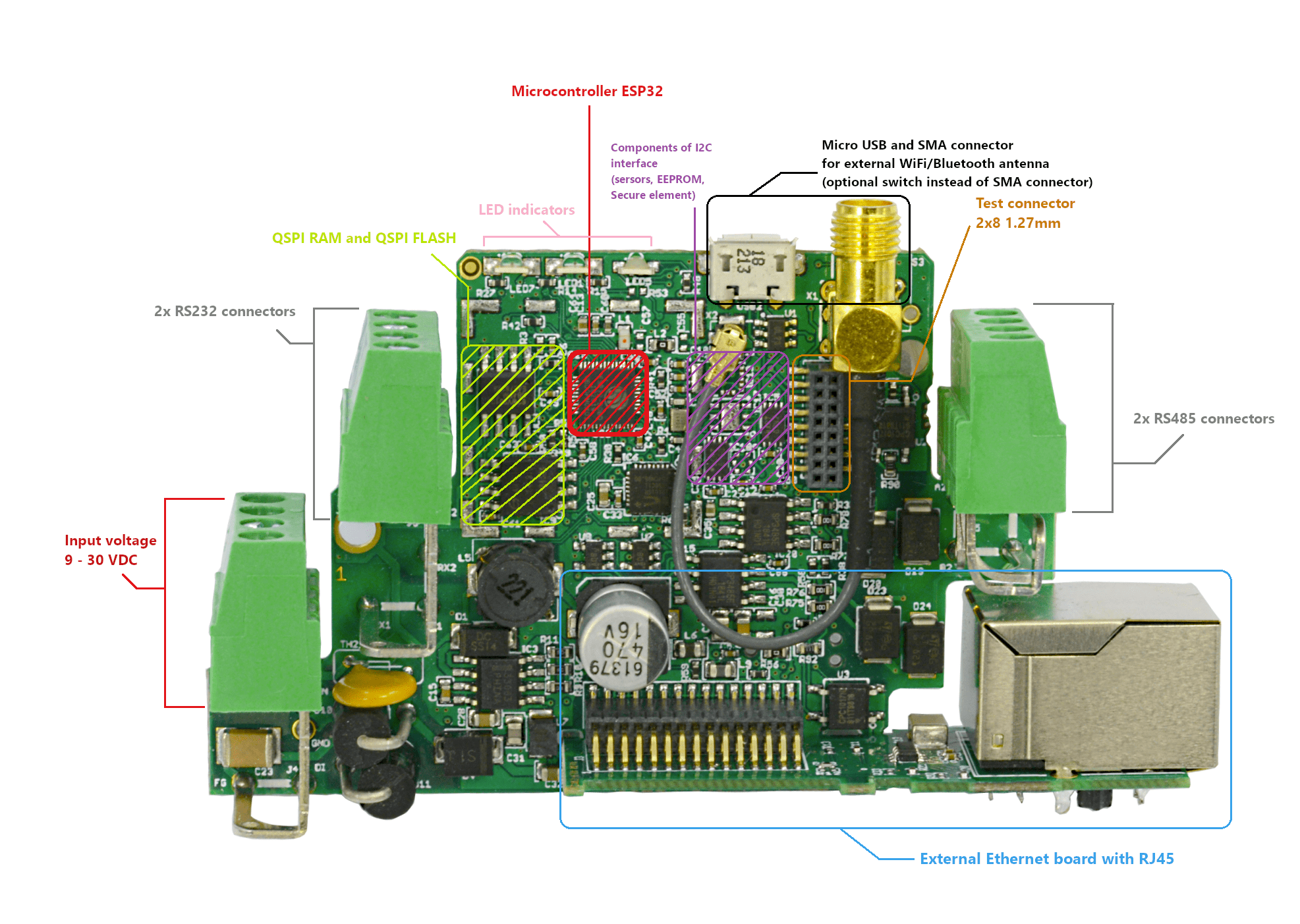
The complete Open IoT and IIoT Gateway kit consists of:
- developer module
- RJ45 network adapter
- hardware programmer
Power input pinout
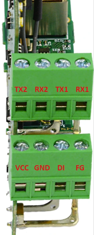
- VCC - power supply input 9-30 VDC
- GND - power supply ground
- DI - digital input (used while there is no button mounted and it can be shorten only to GND)
- FG - frame ground
Test connectors
Provided test connectors can be used for board debugging.
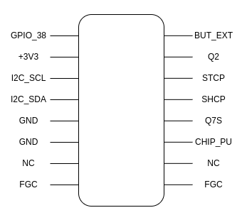
- GPIO_38 - ESP32 general purpose input
- 3V3 - 3.3 VDC
- I2C_SCL, I2C_SDA - I2C connectors
- GND - ground
- NC - not connected
- FGC - frame ground connector
- BUT_EXT - button test line (default: high state)
- Q2 - Q2 output of parallel register (74HC595BQ)
- STCP - clock input of serial register (74HC595BQ)
- SHCP - clock input of buffer register (74HC595BQ)
- Q7S - output of serial register (74HC595BQ)
- CHIP_PU - chip power up line ('1' - powers chip up)
Button / antenna
The antenna connector can be replaced with a button which can be used for, for example, restoring device to the default configuration, saved in EEPROM.
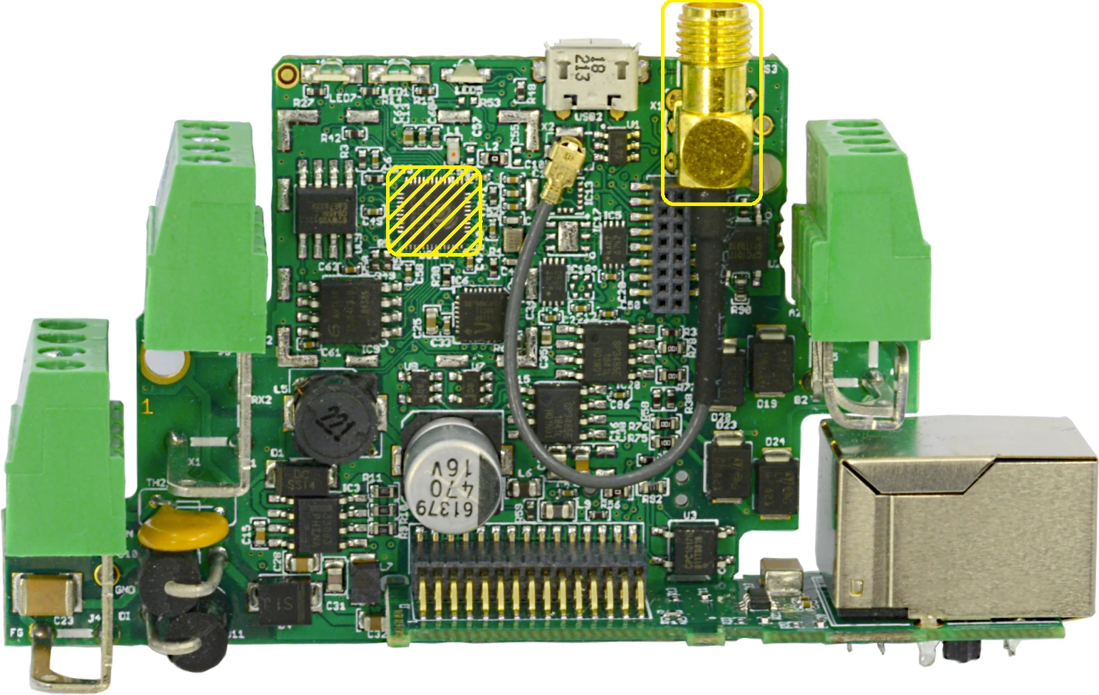
In order to use the button instead of the antenna, the R52 resistor (near the microUSB connector, on the bottom side) has to be soldered to the board.
RS232 ports
The device has 2 independent RS485 ports.
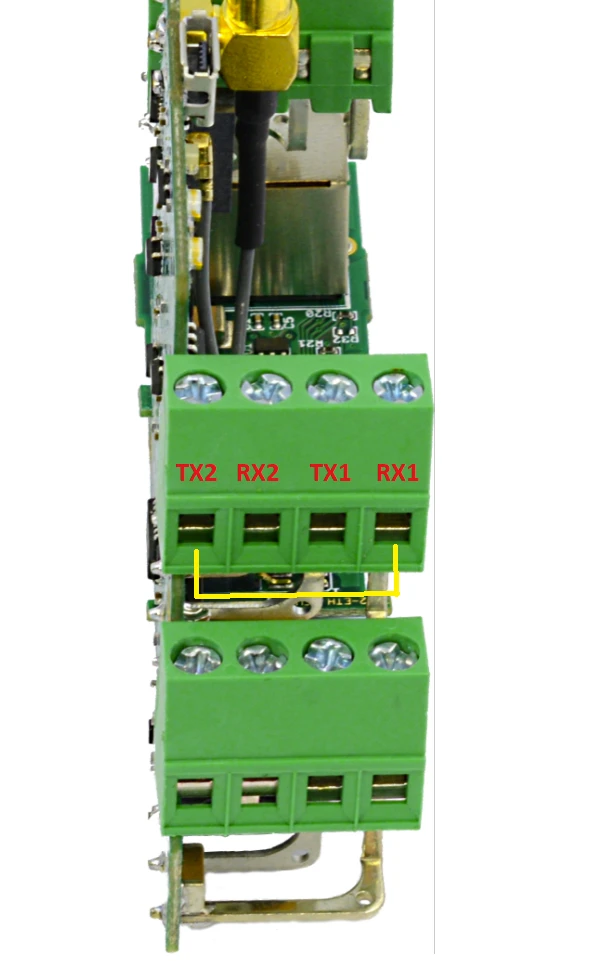
RS485 ports
The device is equipped with two MAX481 transceivers that enable communication in the RS485 standard on two channels independently.
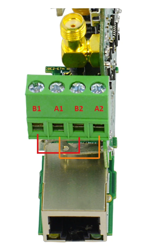
As the RS485_1 / RS232_1 and RS485_2 / RS232_2 standards use common microcontroller serial ports, it is possible to use only 1 interface from the pair at a time.
ETHERNET
In order to support the Ethernet network interface communication, the network adapter available in the kit must be installed on the module (pay attention to its correct installation). This interface is supported by the external IP101G physical layer which communicates with the ESP32 microcontroller.
Programming
The device can be programmed only with the external hardware programmer connected via Tag-Connect connector.