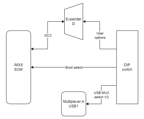
| **Switch No.** | **Positions** | **Description** |
| 1 | OFF - eMMC boot ON - SD card boot | Boot select - switching between booting device |
| 2 | OFF - USB1 OTG ON - UART4 (Linux console) | USB select - microUSB signal choice |
| 3 | OFF - UART1 (SOM user) ON - UART4 (Linux console) | RS232 - SOM UART RS232 select |
| 4 | OFF - UART2 RS232 user ON - ESP32 console | RS232 - SOM UART RS232/ESP32 select |
| 5 | Unassigned | Currently not used |
| 6-8 | OFF/ON | User options |
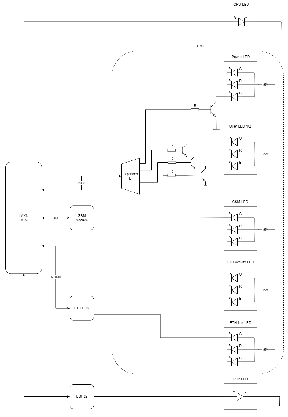
| **Description** | **User-space name** | **Label** |
| Power LED | gpiochip6 9 | "LED\_5V" |
| CPU LED | gpiochip0 3 | "LED\_MAINBOARD" |
| User LED 1 G | gpiochip6 10 | "LED3\_GREEN" |
| User LED 1 R | gpiochip6 5 | "LED3\_RED" |
| User LED 1 B | gpiochip6 12 | "LED3\_BLUE" |
| User LED 2 G | gpiochip6 13 | "LED4\_GREEN" |
| User LED 2 R | gpiochip6 11 | "LED4\_RED" |
| User LED 2 B | gpiochip6 15 | "LED4\_BLUE" |
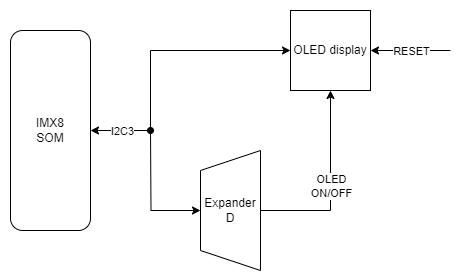
| **OLED pin** | **Description** | **User-space name** |
| RES# | RESET | X |
| SCL | I2C3 clock | X |
| SDA | I2C3 data | X |
| VCC | OLED ON/OFF | gpiochip6 14, "OLED\_EN" |
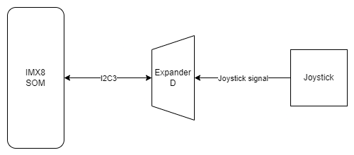
| **Joystick signal** | **Expander D pin** | **User-space name** | **Label** |
| Right | 20 | gpiochip6 3 | "JOY\_RIGHT" |
| Up | 18 | gpiochip6 1 | "JOY\_UP" |
| Left | 17 | gpiochip6 0 | "JOY\_LEFT" |
| Down | 19 | gpiochip6 2 | "JOY\_DOWN" |
| Push | 21 | gpiochip6 4 | "JOY\_PUSH" |