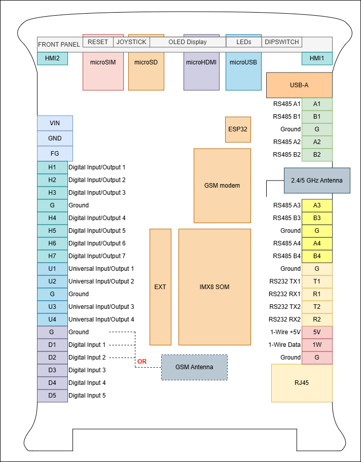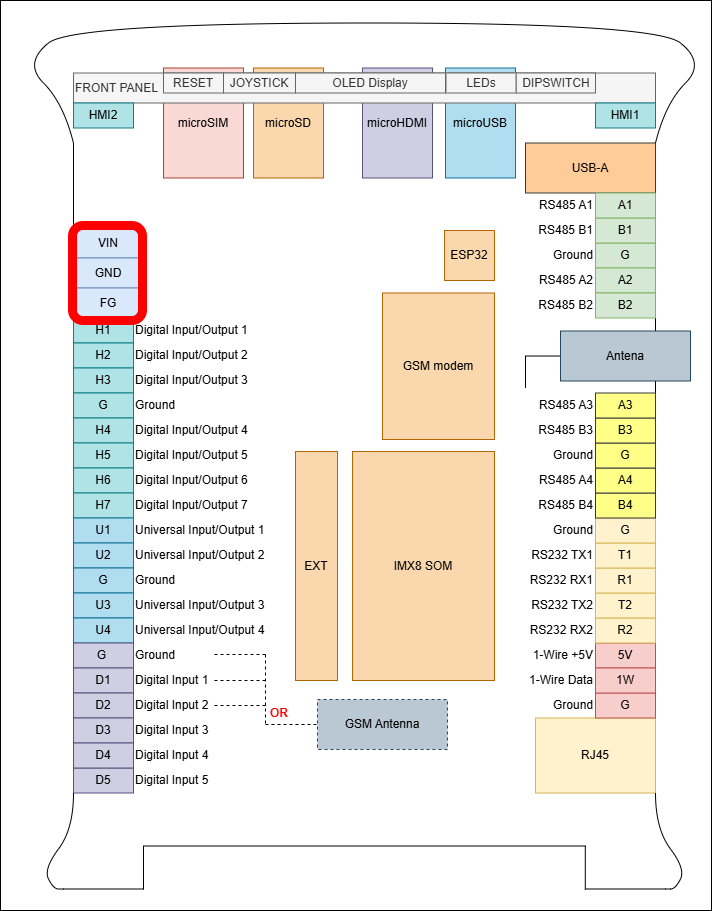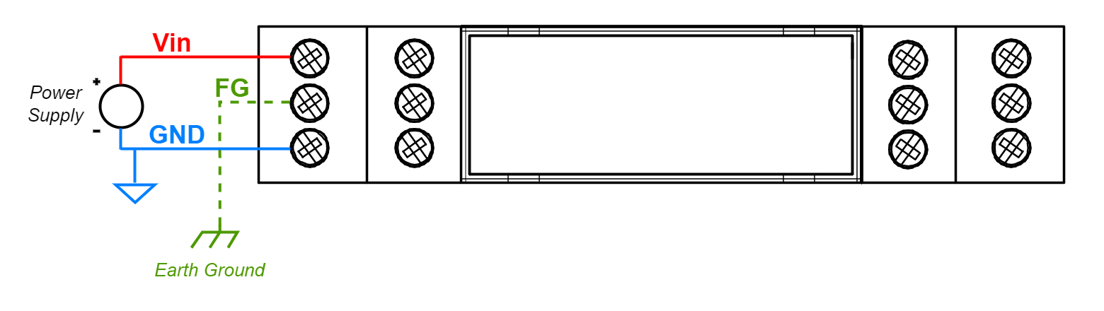
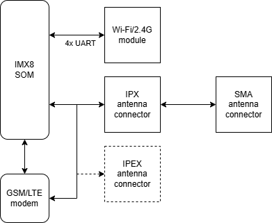
| **TCX IMX8** [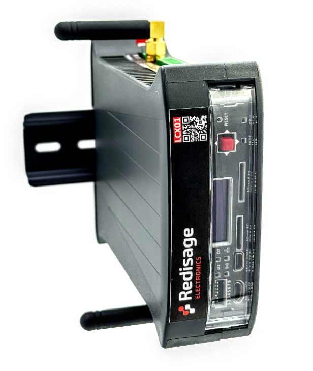](https://doc.redisage.com/uploads/images/gallery/2026-01/p10image.png) | **Features:** - Power: voltage 12-24 VDC +-20%, maximum power 25 W, reverse polarity protection - SoM: VAR-SOM-MX8M-MINI - Core: NXP’s i.MX 8M Mini with 1.6 GHz Quad-core ARM Cortex-A53 and 400 MHz Cortex-M4 real-time processor - Timing: 1.6 GHz - RAM: 2 GB DDR4 - Flash eMMC: 16 GB - 1x microSD connector - 1x microHDMI 1.3a (optional) - 1x microUSB 2.0 HOST / OTG, max. 500 mA (optional) - 1x USB-A 2.0 HOST, max. 1 A - 1x modem GSM SIM7600E + microSIM (optional) - 1x 1-Wire (optional) - 7x DIO - digital input/output, max. 30 V - 4x UIO - universal analog-digital input/output (temperature measurement with sensors, e.g.: Pt1000, Ni1000, KTY, NTC, current, voltage and resistance sensors), max. 20 V (optional) - 3x/5x DI - digital input max. 30 V (optional) - 2x RS232, baudrate 50-115200 bps - 2x RS485, baudrate 50-115200 bps (4x optional) - 1x Ethernet 10/100 Mbps - RJ45 connector - 1x Wi-Fi® / 2.4G module (optional) - 1x secure element (optional) - 1x display OLED 0.87" 128x32 px black&white (optional) - 1x Joystick (optional) - RTC (optional), buzzer, EEPROM - TPM (optional) - Software watchdog |
| **Redisage PN** | **LCX01** | **LCX02** | **LCX03** | **LCX04** | **LCX05** | **LCX06** | |
| **Version** | **Light** | **Light GSM** | **Basic** | **Basic GSM** | **Max** | **Max GSM** | |
| Power input | 12-24 VDC +-20%, maximum power 25 W, reverse polarity protection | ||||||
| System on Module | VAR-SOM-MX8: NXP iMX8M-MINI | ||||||
| Core | NXP’s i.MX 8M Mini with 1.6 GHz Quad-core ARM Cortex-A53 and 400 MHz Cortex-M4 real-time processor | ||||||
| Timing | 1.6 GHz | ||||||
| RAM | 2 GB DDR4 | ||||||
| Flash eMMC | 16GB | ||||||
| Ports/ Connectors | RS232 | 2x | 2x | 2x | 2x | 2x | 2x |
| terminal block max. 2.5 mm2 wire max. 15 m at 115.2 kbps | |||||||
| RS485 | 2x | 2x | 2x | 2x | 4x | 4x | |
| terminal block max. 2.5 mm2 wire max. 1,200 m at 9.6 kbps; max. 400 m at 115.2 kbps | |||||||
| Digital Input |  |  | 5x | 3x | 5x | 3x | |
| Digital Input/Output | 7x | 7x | 7x | 7x | 7x | 7x | |
| Universal Input/Output |  |  | 4x (Current Input, Voltage Input) | 4x (Current Input, Voltage Input) | 4x (Current Input, Voltage Input, Current Output, Resistance) | 4x (Current Input, Voltage Input, Current Output, Resistance) | |
| USB type A |  |  |  |  |  |  | |
| microUSB |  |  |  |  |  |  | |
| 1-Wire |  |  |  |  |  |  | |
| microHDMI |  |  |  |  |  |  | |
| microSD |  |  |  |  |  |  | |
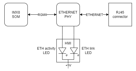
| Ethernet | 10/100 Mb/s Base-T, RJ45 connector | ||||||
| Wi-Fi**®** 2.4/5 GHz 802.11b/g/n/ac SMA Antenna connector |  |  |  |  |  |  | |
| GSM |  |  |  |  |  |  | |
| Joystick |  |  |  |  |  |  | |
| Display OLED 0.87'' 128x32 px black&white |  |  |  |  |  |  | |
| Watchdog | Software WDT on external ESP32 microcontroller | ||||||
| Secure chip |  |  |  |  |  |  | |
| TPM |  |  |  |  |  |  | |
| RTC module |  |  |  |  |  |  | |
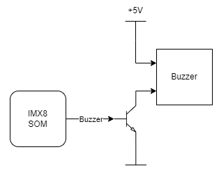
| Buzzer |  |  |  |  |  |  | |
| External Flash |  |  |  |  |  |  | |
| EEPROM |  |  |  |  |  |  | |
| OS | Embedded Linux | ||||||
| Dimensions \[mm\] | 119 x 101 x 22.5 | ||||||
| Work temperature \[°C\] | -40 to +75 | ||||||
| Certification | CE, RoHS, ... | ||||||
| Norms | [Check here](https://doc.redisage.com/link/128#bkmrk-norms) | ||||||
| **Standard** | **Title** | **Description** | **Comments** |
| **Emission** | |||
| EN 61000-6-4 | Generic Emission Standard | Emission standard for industrial environment | |
| EN 55011 | Conducted Emission | Limits for Group 1, Class A | Power port |
| EN 55011 | Radiated Emission | Limits for Group 1, Class A | |
| EN 55032 | Conducted Emission | Limits for Class A | Ethernet port |
| **Immunity** | |||
| EN 61000-6-2 | Generic Emission Standard | Immunity standard for industrial environment | |
| EN 61000-4-2 | Electrostatic discharge (ESD) | ±4kV (contact discharge), ±8kV (air discharge) | |
| EN 61000-4-3 | Radio Frequency immunity | 10V/m | |
| EN 61000-4-4 | Burst/EFT immunity | ±1kV | All ports |
| EN 61000-4-5 | Surge immunity | ±0.5kV (line-to-line), ±1kV (line-to-earth) | Power port |
| EN 61000-4-29 | Voltage Dips, Short Interruptions and Voltage Variations | In progress | Power port |
| **Standard** | **Title** | **Description** | **Comments** |
| EN 61131-2 | Product Standard | Programmable controllers - Part 2: Equipment requirements and tests | |
| EN 60068-2-1 | Cold (storage) | Cold test “storage” suitable for non-heat emitting products. The object of the test is limited to determining the suitability of the components, devices or products for transport or storage at low temperatures. | |
| EN 60068-2-2 | Dry Heat (storage) | Dry heat test “storage” suitable for non-heat emitting products. The object of the test is limited to determining the suitability of the components, devices or products for transport or storage at high temperatures. | |
| EN 60068-2-1 | Cold (operation) | Cold test “operation” suitable for heat emitting products. The object of the test is limited to determining the suitability of the components, devices or products for operation at low temperatures. | |
| EN 60068-2-2 | Dry Heat (operation) | Dry heat test “operation” suitable for heat emitting products. The object of the test is limited to determining the suitability of the components, devices or products for operation at high temperatures. | |
| EN 60068-2-14 | Change of temperature (storage) | The change of temperature test “storage” is suitable for non-heat emitting products. The objective of this test is limited to determining the suitability of the components, devices, or products for operation during temperature changes. | |
| EN 60068-2-14 | Change of temperature (operation) | The change of temperature test “operation” is suitable for heat emitting products. The objective of this test is limited to determining the suitability of the components, devices, or products for operation during temperature changes. | |
| Redisage | Cold start | Cold start test is suitable for non-heat emitting products just before starting the device. The objective of this test is limited to determining the suitability of the devices for start in cold conditions. | |
| EN 60068-2-30 | Damp Heat (storage) | Damp heat test “storage” is suitable for non-heat emitting products. The objective of this test is limited to determining the suitability of the devices for transport or storage under cyclic damp heat conditions. | |
| EN 60068-2-30 | Damp Heat (operation) | Damp heat test “operation” is suitable for non-heat emitting products. The objective of this test is limited to determining the suitability of the devices for transport or storage under cyclic damp heat conditions. |
| **Related information and links** | ||
| [Ordering information](https://redisage.com/en/delivery.html) | [Accessories](https://redisage.com/eng_m_Accessory-174.html) | [Similar products](https://redisage.com/search.php?text=+&sort=name&order=a) |
| **Description** | **Processor pin** | **Default function** |
| 5 V USB voltage | F22 | USB1\_VBUS |
| USB data differential pair negative | A22 | USB1\_D\_N |
| USB data differential pair positive | B22 | USB1\_D\_P |
| USB on the go | AB10 | USB1\_OTG\_PWR |
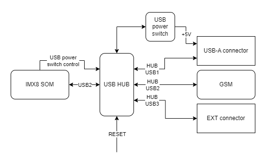
| **Description** | **Processor pin** | **Default function** |
| USB power switch control | F23 | USB2\_VBUS |
| USB data differential pair negative | A23 | USB2\_D\_N |
| USB data differential pair positive | B23 | USB2\_D\_P |
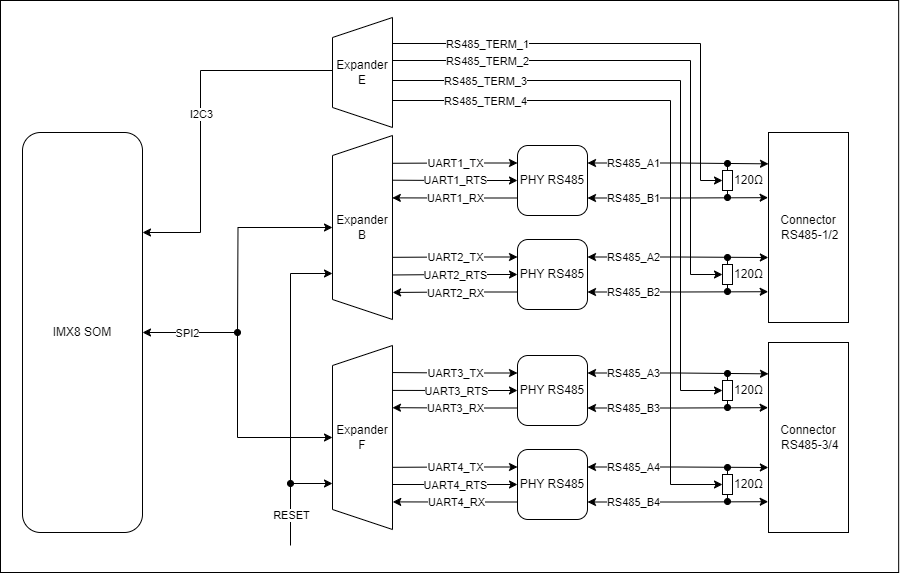
| **Connector pin** | **Description** |
| A1 | RS485 A1 |
| B1 | RS485 B1 |
| G | Ground |
| A2 | RS485 A2 |
| B2 | RS485 B2 |
| **Connector pin** | **Description** |
| A3 | RS485 A3 |
| B3 | RS485 B3 |
| G | Ground |
| A4 | RS485 A4 |
| B4 | RS485 B4 |
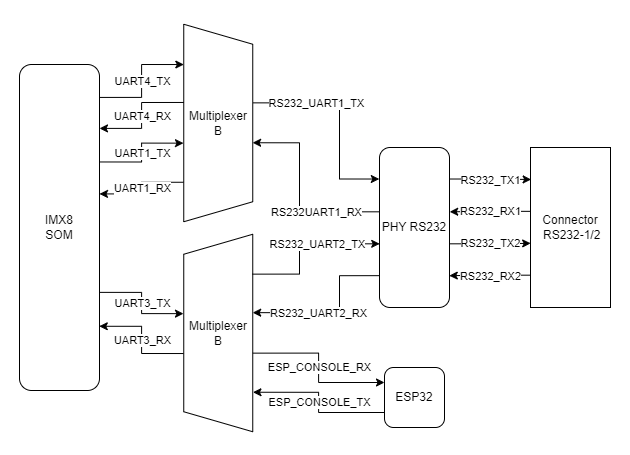
| **Connector pin** | **Description** |
| T1 | RS232 TX1 |
| R1 | RS232 RX1 |
| G | Ground |
| T2 | RS232 TX2 |
| R2 | RS232 RX2 |
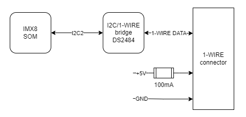
| **Connector pin** | **Description** |
| 1W | 1-Wire data |
| 5V | 1-Wire +5 V power |
| G | Ground |
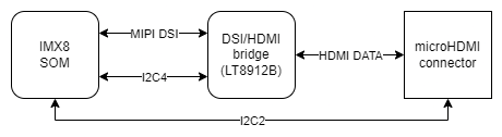
| **Signal** | **Processor pin** | **Default function** |
| DSI\_TX0\_N | A9 | MIPI\_DSI\_TX0\_N |
| DSI\_TX0\_P | B9 | MIPI\_DSI\_TX0\_P |
| DSI\_TX1\_N | A10 | MIPI\_DSI\_TX1\_N |
| DSI\_TX1\_P | B10 | MIPI\_DSI\_TX1\_P |
| DSI\_TX2\_N | A12 | MIPI\_DSI\_TX2\_N |
| DSI\_TX2\_P | B12 | MIPI\_DSI\_TX2\_P |
| DSI\_TX3\_N | A13 | MIPI\_DSI\_TX3\_N |
| DSI\_TX3\_P | B13 | MIPI\_DSI\_TX3\_P |
| DSI\_CLK\_N | A11 | MIPI\_DSI\_CLK\_N |
| DSI\_CLK\_P | B11 | MIPI\_DSI\_CLK\_P |
| **Function** | **Processor pin** | **Default function** |
| USB power switch control | F23 | USB2\_VBUS |
| USB data differential pair negative | A23 | USB2\_D\_N |
| USB data differential pair positive | B23 | USB2\_D\_P |
| **Function** | **Processor pin** | **Default function** |
| SD data line 0 | AB23 | SD2\_DATA0 |
| SD data line 1 | AB24 | SD2\_DATA1 |
| SD data line 2 | V24 | SD2\_DATA2 |
| SD data line 3 | V23 | SD2\_DATA3 |
| SD command line | W24 | SD2\_CMD |
| SD clock | W23 | SD2\_CLK |
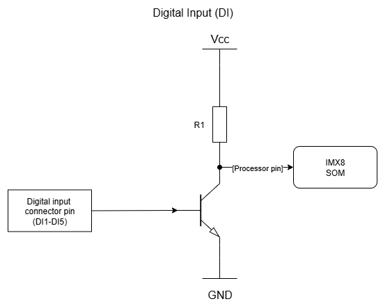
| **DI connector pin** | **Processor pin** | **User-space name** | |
| DI1 | AC22 | gpiochip3 26 | "DI1" |
| DI2 | AD23 | gpiochip3 24 | "DI2" |
| DI3 | AB22 | gpiochip3 22 | "DI3" |
| DI4 | AD15 | gpiochip2 25 | "DI4" |
| DI5 | AC13 | gpiochip2 24 | "DI5" |
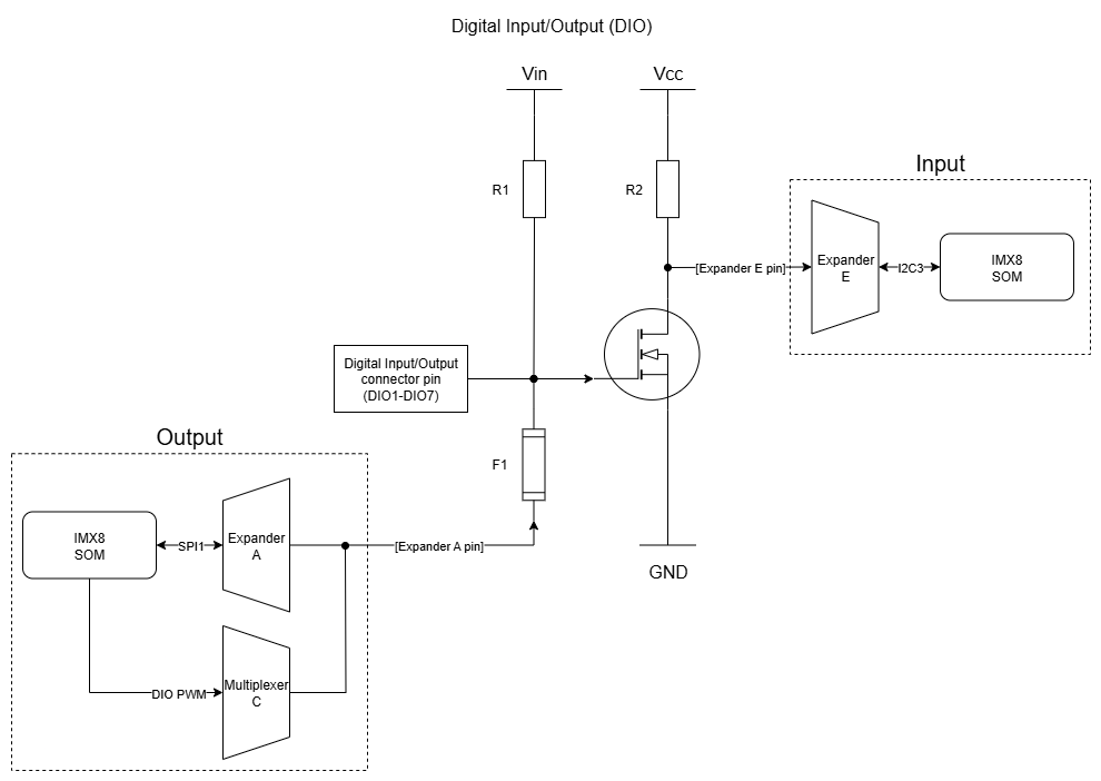
| **DIO connector pin** | **Input** | **Output** | ||
| **User-space name** | **Expander E pin** | **User-space name** | **Expander A pin** | |
| DIO1 | gpiochip5 9 | 24 | gpiochip7 1 | 1 |
| DIO2 | gpiochip5 10 | 25 | gpiochip7 2 | 2 |
| DIO3 | gpiochip5 11 | 28 | gpiochip7 3 | 3 |
| DIO4 | gpiochip5 12 | 1 | gpiochip7 4 | 4 |
| DIO5 | gpiochip5 13 | 2 | gpiochip7 5 | 5 |
| DIO6 | gpiochip5 14 | 3 | gpiochip7 6 | 6 |
| DIO7 | gpiochip5 15 | 4 | gpiochip7 7 | 7 |
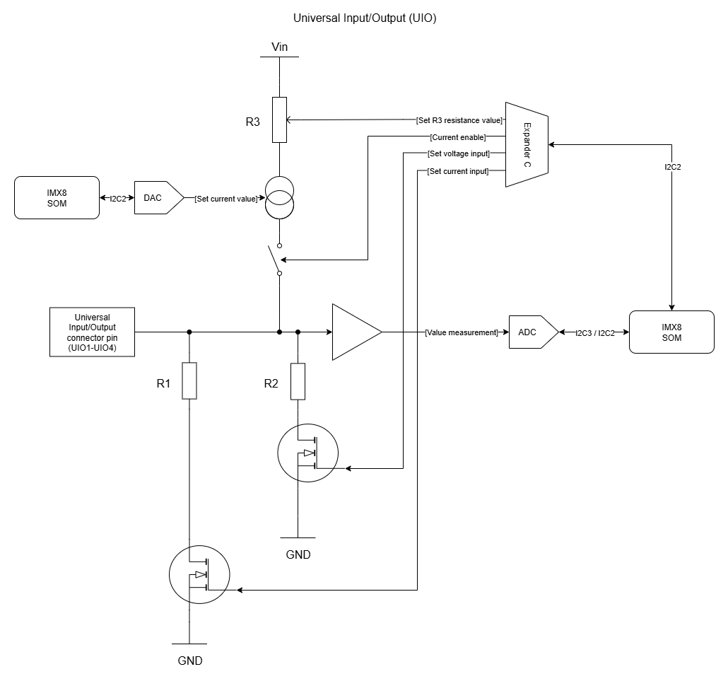
| **Configuration signal** | **Modes of operation** | |||
|---|---|---|---|---|
| **DI dry contact** | **AI 0-10 V** | **AI 0-4-20 mA** | **AO 4-20 mA / temperature\* / resistance** | |
| Set voltage input | 0 | 1 | 0 | 0 |
| Set current input | 0 | 1 | 0 | 1 |
| Current enable | 1 | 0 | 0 | 1 |
| Set R3 resistance value | 1 | X | X | 1 or 0\*\* |
| Set current value | 12-bit value\*\*\* | X | X | 12-bit value\*\*\* |
| **UIO connector pin** | **Configuration signal** | **Expander C pin** |
| UIO1 | Current enable | 20 |
| Set voltage input | 19 | |
| Set current input | 27 | |
| Set R3 resistance value | 21 | |
| UIO2 | Current enable | 3 |
| Set voltage input | 22 | |
| Set current input | 28 | |
| Set R3 resistance value | 4 | |
| UIO3 | Current enable | 23 |
| Set voltage input | 17 | |
| Set current input | 1 | |
| Set R3 resistance value | 18 | |
| UIO4 | Current enable | 26 |
| Set voltage input | 24 | |
| Set current input | 2 | |
| Set R3 resistance value | 25 |
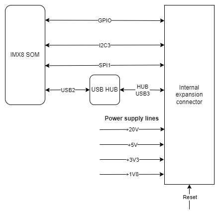
| **Connector pin** | **Description** |
| 1 | GND |
| 2 | VIN |
| 3 | GND |
| 4 | SPI1 MOSI |
| 5 | GND |
| 6 | SPI1 SCLK |
| 7 | GND |
| 8 | SPI1 MISO |
| 9 | GND |
| 10 | RTC battery power supply |
| 11 | External watchdog reset |
| 12 | NC |
| 13 | GND |
| 14 | NC |
| 15 | NC |
| 16 | NC |
| 17 | GPIO4 IO25 |
| 18 | GND |
| 19 | GPIO1 IO07 |
| 20 | GPIO4 IO21 |
| 21 | GPIO5 IO09 |
| 22 | Global reset |
| 23 | GND |
| 24 | I2C3 SDA |
| 25 | I2C3 SCL |
| 26 | GND |
| 27 | +3V3 |
| 28 | GND |
| 29 | USB3 positive pole |
| 30 | USB3 negative pole |
| 31 | GND |
| 32 | +20V |
| 33 | UIO reset |
| 34 | NC |
| 35 | NC |
| 36 | +1V8 |
| 37 | +1V8 |
| 38 | GND |
| 39 | +5V |
| 40 | +5V |
| 41 | GND |
| 42 | GND |
| 43 | VIN |
| 44 | GND |
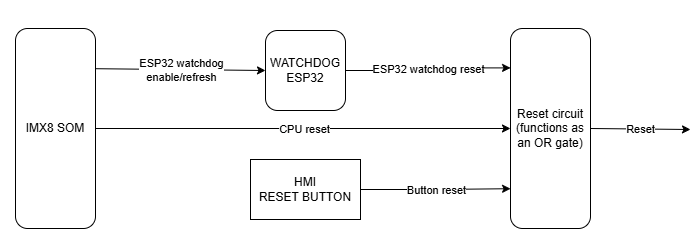
| **Signal** | **Default function** | **User-space name ** | |
| ESP32\_WDI | GPIO1\_IO01 | gpiochip0 1 | ESP32\_WDI |
| SOM\_GLOB\_NRST | GPIO5\_IO02 | gpiochip4 2 | GLOBAL\_NRST |
| GPIO0 | GPIO3\_IO22 | gpiochip2 22 | ESP\_GPIO0 |
| GPIO2 | GPIO3\_IO20 | gpiochip2 20 | ESP\_GPIO2 |
| ESP\_CHIP\_PU | GPIO4\_IO20 | gpiochip3 20 | ESP\_CHIP\_PU |
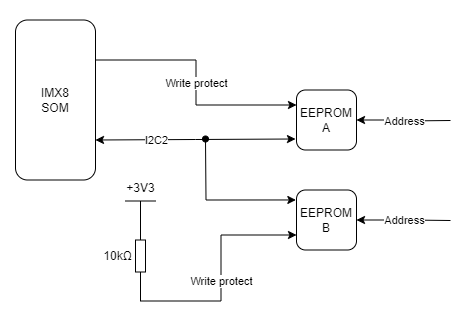
| **EEPROM pin** | **Description** | **User-space name** |
| 1 | Address pin 0 (GND) | X |
| 2 | Address pin 1 (+3V3) | X |
| 3 | Address pin 2 (+3V3) | X |
| 5 | I2C2 data | X |
| 6 | I2C2 clock | X |
| 7 | EEPROM write-protect | gpiochip0 2 |
| **EEPROM pin** | **Description** | **User-space name** |
| 1 | Address pin 0 (GND) | X |
| 2 | Address pin 1 (+3V3) | X |
| 3 | Address pin 2 (GND) | X |
| 5 | I2C2 data | X |
| 6 | I2C2 clock | X |
| 7 | EEPROM write-protect (pull-up) | X |
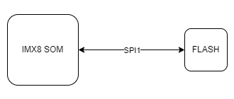
| **FLASH pin** | **Description** | **User-space name** |
| 1 | SPI1\_CS0 | gpiochip2 21 |
| 2 | SPI1\_MISO | X |
| 3 | SPI1\_WP | X |
| 5 | SPI1\_MOSI | X |
| 6 | SPI1\_SCLK | X |
| 7 | SPI1\_HOLD | X |
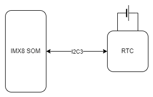
| **RTC pin** | **Description** |
| 1 | Clock oscillator pin no. 1 |
| 2 | Clock oscillator pin no. 2 |
| 3 | Battery power pin |
| 5 | I2C3 data |
| 6 | I2C3 clock |
| **ESP32 pin** | **Description** |
| 8 | ESP\_P\_DETECT |
| 9 | ESP\_CHIP\_PU |
| 14 | ESP32\_WDT\_EN |
| 15 | ESP32\_WDI |
| 22 | ESP\_GPIO2 |
| 23 | ESP\_GPIO0 |
| 24 | RESET\_WDT |
| 25 | LED\_ESP |
| 26 | VDD\_SDIO |
| 28 | ESP\_SPI\_HD |
| 29 | ESP\_SPI\_WP |
| 30 | ESP\_SPI\_CS0 |
| 31 | ESP\_SPI\_CLK |
| 32 | ESP\_SPI\_Q |
| 33 | ESP\_SPI\_D |
| 38 | I2C4\_SCL |
| 39 | I2C4\_SDA |
| 40 | ESP\_CONSOLE\_RX |
| 41 | ESP\_CONSOLE\_TX |
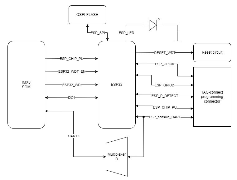
| **Signal** | **CPU pin** | **Default function** | **User-space name** |
| ESP\_GPIO\_0 | AC14 | GPIO3\_IO22 | gpiochip2 22 |
| ESP\_GPIO\_2 | AC15 | GPIO3\_IO20 | gpiochip2 20 |
| ESP32\_WDI | AF14 | GPIO1\_IO01 | gpiochip0 1 |
| ESP32\_WDT\_EN | AF13 | GPIO1\_IO03 | gpiochip0 3 |
| **TPM pin** | **Description** |
| 17 | Reset |
| 18 | TPM\_IRQ |
| 19 | SPI2 clock |
| 20 | SPI2 chip select 0 |
| 21 | SPI2 master out slave in |
| 24 | SPI2 master in slave out |
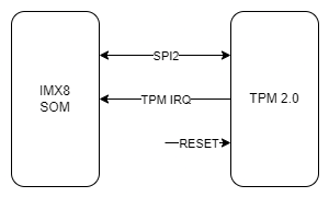
| **Signal** | **CPU pin** | **Default function** | **User-space name** |
| TPM\_IRQ | AC24 | GPIO4\_IO23 | gpiochip3 23 |
| SPI2\_CS0\_TPM | A6 | GPIO5\_IO13 | gpiochip4 13 |
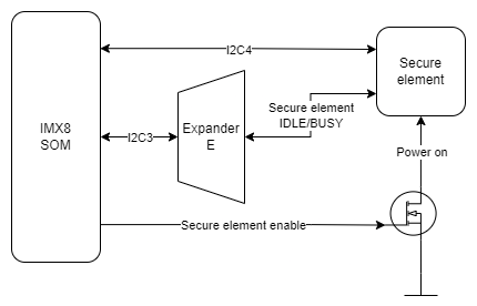
| **Secure element pin** | **Description** |
| 1 | I2C4 clock |
| 2 | I2C4 data |
| 3 | +3V3 |
| 6 | IDLE/BUSY state report |
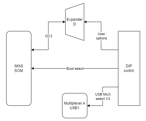
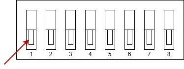
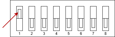
| **Switch No.** | **Positions** | **Description** |
| 1 | OFF - eMMC boot ON - SD card boot | Boot select - switching between booting device |
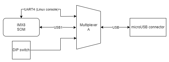
| 2 | OFF - USB1 OTG ON - UART4 (Linux console) | USB select - microUSB signal choice |
| 3 | OFF - UART1 (SOM user) ON - UART4 (Linux console) | RS232 - SOM UART RS232 select |
| 4 | OFF - UART2 RS232 user ON - ESP32 console | RS232 - SOM UART RS232/ESP32 select |
| 5 | Unassigned | Currently not used |
| 6-8 | OFF/ON | User options |
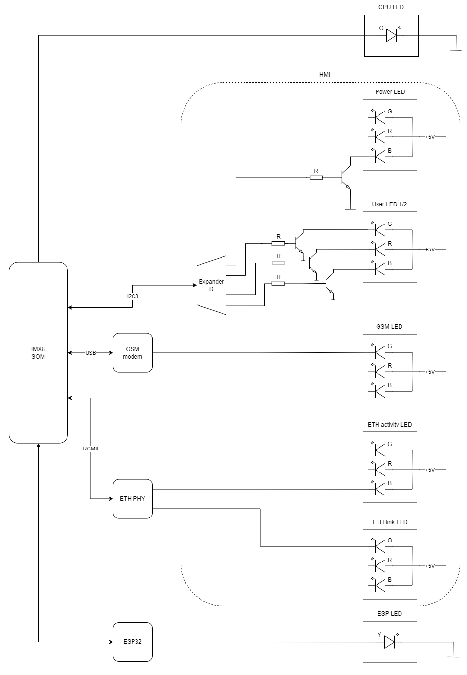
| **Description** | **User-space name** | **Label** |
| Power LED | gpiochip6 9 | "LED\_5V" |
| CPU LED | gpiochip0 3 | "LED\_MAINBOARD" |
| User LED 1 G | gpiochip6 10 | "LED3\_GREEN" |
| User LED 1 R | gpiochip6 5 | "LED3\_RED" |
| User LED 1 B | gpiochip6 12 | "LED3\_BLUE" |
| User LED 2 G | gpiochip6 13 | "LED4\_GREEN" |
| User LED 2 R | gpiochip6 11 | "LED4\_RED" |
| User LED 2 B | gpiochip6 15 | "LED4\_BLUE" |
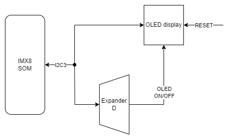
| **OLED pin** | **Description** | **User-space name** |
| RES# | RESET | X |
| SCL | I2C3 clock | X |
| SDA | I2C3 data | X |
| VCC | OLED ON/OFF | gpiochip6 14, "OLED\_EN" |
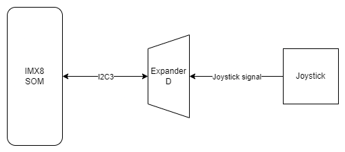
| **Joystick signal** | **Expander D pin** | **User-space name** | **Label** |
| Right | 20 | gpiochip6 3 | "JOY\_RIGHT" |
| Up | 18 | gpiochip6 1 | "JOY\_UP" |
| Left | 17 | gpiochip6 0 | "JOY\_LEFT" |
| Down | 19 | gpiochip6 2 | "JOY\_DOWN" |
| Push | 21 | gpiochip6 4 | "JOY\_PUSH" |
| **Pin** | **Type** | **Usage** | **User-space name** | **Description** |
| 1 | Q1 | DO1 | gpiochip8 1 | Digital output 1 |
| 2 | Q2 | DO2 | gpiochip8 2 | Digital output 2 |
| 3 | Q3 | DO3 | gpiochip8 3 | Digital output 3 |
| 4 | Q4 | DO4 | gpiochip8 4 | Digital output 4 |
| 5 | Q5 | DO5 | gpiochip8 5 | Digital output 5 |
| 6 | Q6 | DO6 | gpiochip8 6 | Digital output 6 |
| 7 | Q7 | DO7 | gpiochip8 7 | Digital output 7 |
| 9 | Q7S | NC | X | Not connected |
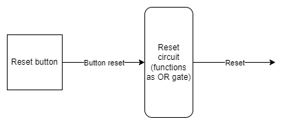
| 10 | MR/ | NRST\_GLOBAL | X | Reset |
| 11 | SHCP | SPI1\_SCLK | X | SPI clock |
| 12 | STCP | SPI1\_CS1 | X | SPI chip select |
| 13 | OE/ | GND | X | Output enable |
| 14 | DS | SPI1\_MOSI | X | SPI master out slave in |
| 15 | Q0 | MUX\_DIO\_SEL | gpiochip8 0 | MUX\_PWM selection signal |
| 16 | VCC | +3V3 | X | Power supply |
| **Pin** | **Type** | **Usage** | **User-space name** | **Description** |
| 1 | RXA(I) | RS485\_UART1\_RX | X | RS485 UART1 RX |
| 2 | RESET/ | RS485\_NRST | X | Reset |
| 3 | XTAL1(I) | TXCO\_OUT | X | Oscillator output |
| 4 | XTAL2(O) | NC | X | Not connected |
| 5 | VDD | +3V3 | X | Power supply |
| 6 | I2C / SPI/ | GND | X | Ground |
| 7 | CS/ / A0 | SPI2\_CS1 | X | SPI chip select |
| 8 | SI / A1 | SPI2\_MOSI | X | SPI master out slave in |
| 9 | SO | SPI2\_MISO | X | SPI master in slave out |
| 10 | SCL / SCLK | SPI2\_SCLK | X | SPI clock |
| 11 | SDA / VSS | GND | X | Ground |
| 12 | VSS | GND | X | Ground |
| 14 | IRQ/ | RS485\_INT | X | RS485 interrupt |
| 15 | CTSB/ | NC | X | Not connected |
| 16 | RTSB/ | RS485\_UART2\_RTS | X | RS485 UART2 RTS |
| 17 | GPIO0 / DSRB/ | NC | X | Not connected |
| 18 | GPIO1 / DTRB/ | NC | X | Not connected |
| 19 | GPIO2 / CDB/ | NC | X | Not connected |
| 20 | GPIO3 / RIB/ | NC | X | Not connected |
| 22 | TXB(O) | RS485\_UART2\_TX | X | RS485 UART2 TX |
| 23 | RXB(I) | RS485\_UART2\_RX | X | RS485 UART2 RX |
| 24 | GPIO4 / DSRA/ | NC | X | Not connected |
| 25 | GPIO5 / DTRA/ | NC | X | Not connected |
| 26 | GPIO6 / CDA/ | NC | X | Not connected |
| 27 | GPIO7 / RIA/ | NC | X | Not connected |
| 30 | RTSA/ | RS485\_UART1\_RTS | X | RS485 UART1 RTS |
| 31 | CTSA/ | NC | X | Not connected |
| 32 | TXA(O) | RS485\_UART1\_TX | X | RS485 UART1 TX |
| **Pin** | **Port** | **Type** | **User-space name** | **Description** |
| 1 | GPB4 | GPIO | gpiochip5 12 | UIO4 voltage |
| 2 | GPB5 | GPIO | gpiochip5 13 | UIO4 current |
| 3 | GPB6 | GPIO | gpiochip5 14 | UIO4 resistance |
| 4 | GPB7 | GPIO | gpiochip5 15 | UIO3 resistance |
| 5 | VDD | +3V3 | X | Power supply |
| 6 | VSS | GND | X | Ground |
| 7 | NC | NC | X | Not connected |
| 8 | SCK | GPIO | X | I2C clock |
| 9 | SDA | GPIO | X | I2C data |
| 10 | NC | NC | X | Not connected |
| 11 | A0 | GND | X | Address bit 0 |
| 12 | A1 | GND | X | Address bit 1 |
| 13 | A2 | GND | X | Address bit 2 |
| 14 | RESET/ | EXP2\_NRST | X | Reset |
| 15 | INTB | NC | X | Not connected |
| 16 | INTA | NC | X | Not connected |
| 17 | GPA0 | GPIO | gpiochip5 0 | UIO2 resistance |
| 18 | GPA1 | GPIO | gpiochip5 1 | UIO1 resistance |
| 19 | GPA2 | GPIO | gpiochip5 2 | UIO1 voltage |
| 20 | GPA3 | GPIO | gpiochip5 3 | UIO2 voltage |
| 21 | GPA4 | GPIO | gpiochip5 4 | UIO3 voltage |
| 22 | GPA5 | GPIO | gpiochip5 5 | UIO1 current |
| 23 | GPA6 | GPO | gpiochip5 6 | UIO4 I source |
| 24 | GPA7 | GPIO | gpiochip5 7 | UIO3 current |
| 25 | GPB0 | GPIO | gpiochip5 8 | UIO2 current |
| 26 | GPB1 | GPO | gpiochip5 9 | UIO1 I source |
| 27 | GPB2 | GPO | gpiochip5 10 | UIO2 I source |
| 28 | GPB3 | GPO | gpiochip5 11 | UIO3 I source |
| **Pin** | **Port** | **Type** | **User-space name** | **Description** |
| 1 | GPB4 | GPO | gpiochip6 12 | LED3 BLUE ON / OFF |
| 2 | GPB5 | GPO | gpiochip6 13 | LED4 GREEN ON / OFF |
| 3 | GPB6 | GPO | gpiochip6 14 | OLED ON / OFF |
| 4 | GPB7 | GPO | gpiochip6 15 | LED4 BLUE ON / OFF |
| 5 | VDD | +3V3 | X | Power supply |
| 6 | VSS | GND | X | Ground |
| 7 | NC1 | NC | X | Not connected |
| 8 | SCK | GPIO | X | I2C clock |
| 9 | SDA | GPIO | X | I2C data |
| 10 | NC2 | NC | X | Not connected |
| 11 | A0 | GND | X | Address bit 0 |
| 12 | A1 | GND | X | Address bit 1 |
| 13 | A2 | GND | X | Address bit 2 |
| 14 | RESET/ | NRST\_GLOBAL | X | Reset |
| 15 | INTB | HMI\_IRQ | X | Interrupt B |
| 16 | INTA | HMI\_IRQ | X | Interrupt A |
| 17 | GPA0 | GPI | gpiochip6 0 | Joystick left input |
| 18 | GPA1 | GPI | gpiochip6 1 | Joystick up input |
| 19 | GPA2 | GPI | gpiochip6 2 | Joystick down input |
| 20 | GPA3 | GPI | gpiochip6 3 | Joystick right input |
| 21 | GPA4 | GPI | gpiochip6 4 | Joystick push input |
| 22 | GPA5 | GPO | gpiochip6 5 | LED3 RED ON / OFF |
| 23 | GPA6 | GPI | gpiochip6 6 | DIP switch 6 input |
| 24 | GPA7 | GPI | gpiochip6 7 | DIP switch 7 input |
| 25 | GPB0 | GPI | gpiochip6 8 | DIP switch 8 input |
| 26 | GPB1 | GPO | gpiochip6 9 | LED 5 V power supply ON / OFF |
| 27 | GPB2 | GPO | gpiochip6 10 | LED3 GREEN ON / OFF |
| 28 | GPB3 | GPO | gpiochip6 11 | LED4 RED ON / OFF |
| **Pin** | **Port** | **Type** | **User-space name** | **Description** |
| 1 | GPB4 | GPI | gpiochip5 12 | Digital input 4 (DIO circuit) |
| 2 | GPB5 | GPI | gpiochip5 13 | Digital input 5 (DIO circuit) |
| 3 | GPB6 | GPI | gpiochip5 14 | Digital input 6 (DIO circuit) |
| 4 | GPB7 | GPI | gpiochip5 15 | Digital input 7 (DIO circuit) |
| 5 | VDD | +3V3 | X | Power supply |
| 6 | VSS | GND | X | Ground |
| 7 | NC | NC | X | Not connected |
| 8 | SCK | GPIO | X | I2C clock |
| 9 | SDA | GPIO | X | I2C data |
| 10 | NC | NC | X | Not connected |
| 11 | A0 | +3V3 | X | Address bit 0 |
| 12 | A1 | +3V3 | X | Address bit 1 |
| 13 | A2 | GND | X | Address bit 2 |
| 14 | RESET/ | EXP1\_NRST | X | Reset |
| 15 | INTB | GPIO\_EXP\_INT | X | Interrupt B |
| 16 | INTA | GPIO\_EXP\_INT | X | Interrupt A |
| 17 | GPA0 | GPO | gpiochip5 0 | Termination RS485\_4 ON / OFF |
| 18 | GPA1 | GPO | gpiochip5 1 | Termination RS485\_3 ON / OFF |
| 19 | GPA2 | GPO | gpiochip5 2 | Termination RS485\_2 ON / OFF |
| 20 | GPA3 | GPO | gpiochip5 3 | Termination RS485\_1 ON / OFF |
| 21 | GPA4 | NC | X | Not connected |
| 22 | GPA5 | NC | X | Not connected |
| 23 | GPA6 | GPO | gpiochip5 6 | Secure chip idle/busy |
| 24 | GPA7 | GPI | gpiochip5 7 | Digital input 1 (DIO circuit) |
| 25 | GPB0 | GPO | gpiochip5 8 | Digital input 2 (DIO circuit) |
| 26 | GPB1 | GPI | gpiochip5 9 | SD detect |
| 27 | GPB2 | GPI | gpiochip5 10 | VIN level error |
| 28 | GPB3 | GPI | gpiochip5 11 | Digital input 3 (DIO circuit) |
| **Pin** | **Type** | **Usage** | **User-space name** | **Description** |
| 1 | RXA(I) | RS485\_UART4\_RX | X | RS485 UART4 RX |
| 2 | RESET/ | RS485\_NRST | X | Reset |
| 3 | XTAL1(I) | TXCO\_OUT | X | Oscillator output |
| 4 | XTAL2(O) | NC | X | Not connected |
| 5 | VDD | +3V3 | X | Power supply |
| 6 | I2C / SPI/ | GND | X | Ground |
| 7 | CS/ / A0 | SPI2\_CS2 | X | SPI chip select |
| 8 | SI / A1 | SPI2\_MOSI | X | SPI master out slave in |
| 9 | SO | SPI2\_MISO | X | SPI master in slave out |
| 10 | SCL / SCLK | SPI2\_SCLK | X | SPI clock |
| 11 | SDA / VSS | GND | X | Ground |
| 12 | VSS | GND | X | Ground |
| 14 | IRQ/ | RS485\_INT | X | RS485 interrupt |
| 15 | CTSB/ | NC | X | Not connected |
| 16 | RTSB/ | RS485\_UART3\_RTS | X | RS485 UART3 RTS |
| 17 | GPIO0 / DSRB/ | NC | X | Not connected |
| 18 | GPIO1 / DTRB/ | NC | X | Not connected |
| 19 | GPIO2 / CDB/ | NC | X | Not connected |
| 20 | GPIO3 / RIB/ | NC | X | Not connected |
| 22 | TXB(O) | RS485\_UART3\_TX | X | RS485 UART3 TX |
| 23 | RXB(I) | RS485\_UART3\_RX | X | RS485 UART3 RX |
| 24 | GPIO4 / DSRA/ | NC | X | Not connected |
| 25 | GPIO5 / DTRA/ | NC | X | Not connected |
| 26 | GPIO6 / CDA/ | NC | X | Not connected |
| 27 | GPIO7 / RIA/ | NC | X | Not connected |
| 30 | RTSA/ | RS485\_UART4\_RTS | X | RS485 UART4 RTS |
| 31 | CTSA/ | NC | X | Not connected |
| 32 | TXA(O) | RS485\_UART4\_TX | X | RS485 UART4 TX |
| **Eagle designation** | **Documentation designation** |
| **Digital inputs connectors** | |
| 1 | G |
| 2 | D1 |
| 3 | D2 |
| 4 | D3 |
| 5 | D4 |
| 6 | D5 |
| **Digital inputs/outputs connectors** | |
| 1 | H1 |
| 2 | H2 |
| 3 | H3 |
| 4 | G |
| 5 | H4 |
| 6 | H5 |
| 7 | H6 |
| 8 | H7 |
| **Universal inputs/outputs connector** | |
| 1 | U1 |
| 2 | U2 |
| 3 | G |
| 4 | U3 |
| 5 | U4 |
| **RS485 1/2 connectors** | |
| 1 | A1 |
| 2 | B1 |
| 3 | G |
| 4 | A2 |
| 5 | B2 |
| **RS485 3/4 connectors** | |
| 1 | A3 |
| 2 | B3 |
| 3 | G |
| 4 | A4 |
| 5 | B4 |
| **RS232 1/2 & 1-Wire connectors** | |
| 1 | G |
| 2 | T1 |
| 3 | R1 |
| 4 | T2 |
| 5 | R2 |
| 6 | 1W |
| 7 | 5V |
| 8 | G |
| Bits per second | 115200 |
| Data bits | 8 |
| Parity | None |
| Stop bits | 1 |
Warning! Update files are the default version of firmware. All updates factory reset the device. Make sure you backup all of your important files.
# System Overview ## {{@273#bkmrk-tiger-city-imx-embed}} ### Distribution Custom Linux distribution based on the Yocto Project. Type `uname -a` to check installed version, kernel, etc. ### Supported languages - English (US) - English (GB) ### User utilities #### Text editor The default available built-in text editor on the device is `vim`. #### Wi-Fi The device is equipped with a Wi-Fi module and a NetworkManager library, which allows it to connect to nearby wireless networks. ##### How to enable and connect with WLAN: 1. Check the library status: `systemctl status NetworkManager` 2. If NetworkManager is disabled, type `systemctl start NetworkManager` 3. It is possible to enable it always with autostart: `systemctl enable NetworkManager` 4. Search available networks: `nmcli dev wifi list` 5. Connect with your chosen network: `nmcli dev wifi connectThis example won’t work in the loopback connection test - an external serial monitor is needed.
#### Connections In order to test, the program uses **T1, R1, T2, R2** and **GND** pins (diagram provided at the bottom of this page). ### RS485 This example shows how to write to and read from the RS485 interface of the Tiger computer. - [RS485 - C example](https://github.com/Redisage/Tiger-City-IMX-Software-Examples/blob/main/c/RS485.c) - [RS485 - Python example](https://github.com/Redisage/Tiger-City-IMX-Software-Examples/blob/main/python/RS485.py) - [RS485 - Bash example](https://github.com/Redisage/Tiger-City-IMX-Software-Examples/blob/main/scripts/RS485.sh)This example won’t work in the loopback connection test - an external serial monitor is needed.
#### Connections In order to test, the program uses **A1 - A4, B1 - B4** and **GND** pins (diagram provided at the bottom of this page). ### UIO AI 10 V This example shows how to use the UIO (Universal Input Output) of the Tiger computer as a voltage AI (Analog Input). - [UIO\_AI\_10V - C example](https://github.com/Redisage/Tiger-City-IMX-Software-Examples/blob/main/c/UIO_AI_10V.c) - [UIO\_AI\_10V - Python example](https://github.com/Redisage/Tiger-City-IMX-Software-Examples/blob/main/python/UIO_AI_10V.py) - [UIO\_AI\_10V - Bash example](https://github.com/Redisage/Tiger-City-IMX-Software-Examples/blob/main/scripts/UIO_AI_10V.sh) #### Connections In order to test, the program uses **U1 - U4** pins (diagram provided at the bottom of this page). ### UIO AI 20 mA This example shows how to use the UIO (Universal Input Output) of the Tiger computer as a current AI (Analog Input). - [UIO\_AI\_20mA - C example](https://github.com/Redisage/Tiger-City-IMX-Software-Examples/blob/main/c/UIO_AI_20mA.c) - [UIO\_AI\_20mA - Python example](https://github.com/Redisage/Tiger-City-IMX-Software-Examples/blob/main/python/UIO_AI_20mA.py) - [UIO\_AI\_20mA - Bash example](https://github.com/Redisage/Tiger-City-IMX-Software-Examples/blob/main/scripts/UIO_AI_20mA.sh) #### Connections In order to test, the program uses **U1 - U4** pins (diagram provided at the bottom of this page). ### UIO AO This example shows how to use the UIO (Universal Input Output) of the Tiger computer as an AO (Analog Output). - [UIO\_AO - C example](https://github.com/Redisage/Tiger-City-IMX-Software-Examples/blob/main/c/UIO_AO.c) - [UIO\_AO - Python example](https://github.com/Redisage/Tiger-City-IMX-Software-Examples/blob/main/python/UIO_AO.py) - [UIO\_AO - Bash example](https://github.com/Redisage/Tiger-City-IMX-Software-Examples/blob/main/scripts/UIO_AO.sh) #### Connections In order to test, the program uses **U1 - U4** pins (diagram provided at the bottom of this page). ### UIO DI This example shows how to use the UIO (Universal Input Output) of the Tiger computer as a DI (Digital Input). - [UIO\_DI - C example](https://github.com/Redisage/Tiger-City-IMX-Software-Examples/blob/main/c/UIO_DI.c) - [UIO\_DI - Python example](https://github.com/Redisage/Tiger-City-IMX-Software-Examples/blob/main/python/UIO_DI.py) - [UIO\_DI - Bash example](https://github.com/Redisage/Tiger-City-IMX-Software-Examples/blob/main/scripts/UIO_DI.sh) #### Connections In order to test, the program uses **U1 - U4** pins (diagram provided at the bottom of this page). ### USB This example shows how to open, write to, and read from a USB device plugged into the Tiger computer. - [USB - C example](https://github.com/Redisage/Tiger-City-IMX-Software-Examples/blob/main/c/USB.c) - [USB - Python example](https://github.com/Redisage/Tiger-City-IMX-Software-Examples/blob/main/python/USB.py) - [USB - Bash example](https://github.com/Redisage/Tiger-City-IMX-Software-Examples/blob/main/scripts/USB.sh) #### Connections In order to test, the program uses the USB port (diagram provided at the bottom of this page). ### Wi-Fi This example shows how to connect the Tiger computer to a Wi-Fi access point. - [Wi-Fi - C example](https://github.com/Redisage/Tiger-City-IMX-Software-Examples/blob/main/c/WIFI.c) - [Wi-Fi - Python example](https://github.com/Redisage/Tiger-City-IMX-Software-Examples/blob/main/python/WIFI.py) - [Wi-Fi - Bash example](https://github.com/Redisage/Tiger-City-IMX-Software-Examples/blob/main/scripts/WIFI.sh) ### Ports diagram {{@274#bkmrk-}} # Internal Devices ## {{@273#bkmrk-tiger-city-imx-embed}} ### Buzzer This example shows how to use the integrated buzzer of the Tiger computer. The buzzer will generate a sound for a few seconds and then turn itself off. - [Buzzer - C example](https://github.com/Redisage/Tiger-City-IMX-Software-Examples/blob/main/c/buzzer.c) - [buzzer - Python example](https://github.com/Redisage/Tiger-City-IMX-Software-Examples/blob/main/python/buzzer.py) - [Buzzer - Bash example](https://github.com/Redisage/Tiger-City-IMX-Software-Examples/blob/main/scripts/buzzer.sh) ### EEPROM erase This example shows how to erase the EEPROM memory of the Tiger computer. - [EEPROM\_erase - C example](https://github.com/Redisage/Tiger-City-IMX-Software-Examples/blob/main/c/EEPROM_erase.c) - [EEPROM\_erase - Python example](https://github.com/Redisage/Tiger-City-IMX-Software-Examples/blob/main/python/EEPROM_erase.py) - [EEPROM\_erase - Bash example](https://github.com/Redisage/Tiger-City-IMX-Software-Examples/blob/main/scripts/EEPROM_erase.sh) ### EEPROM read This example shows how to read from the EEPROM memory of the Tiger computer. - [EEPROM\_read - C example](https://github.com/Redisage/Tiger-City-IMX-Software-Examples/blob/main/c/EEPROM_read.c) - [EEPROM\_read - Python example](https://github.com/Redisage/Tiger-City-IMX-Software-Examples/blob/main/python/EEPROM_read.py) - [EEPROM\_read - Bash example](https://github.com/Redisage/Tiger-City-IMX-Software-Examples/blob/main/scripts/EEPROM_read.sh) ### EEPROM SN read This example shows how to read from the EEPROM SN (read-only) memory of the Tiger computer. - [EEPROM\_SN\_read - C example](https://github.com/Redisage/Tiger-City-IMX-Software-Examples/blob/main/c/EEPROM_SN_read.c) - [EEPROM\_SN\_read - Python example](https://github.com/Redisage/Tiger-City-IMX-Software-Examples/blob/main/python/EEPROM_SN_read.py) - [EEPROM\_SN\_read - Bash example](https://github.com/Redisage/Tiger-City-IMX-Software-Examples/blob/main/scripts/EEPROM_SN_read.sh) ### EEPROM write This example shows how to write some sample string to the EEPROM memory of the Tiger computer. - [EEPROM\_write - C example](https://github.com/Redisage/Tiger-City-IMX-Software-Examples/blob/main/c/EEPROM_write.c) - [EEPROM\_write - Python example](https://github.com/Redisage/Tiger-City-IMX-Software-Examples/blob/main/python/EEPROM_write.py) - [EEPROM\_write - Bash example](https://github.com/Redisage/Tiger-City-IMX-Software-Examples/blob/main/scripts/EEPROM_write.sh) ### FLASH erase This example shows how to erase the FLASH memory of the Tiger computer. - [FLASH\_erase - C example](https://github.com/Redisage/Tiger-City-IMX-Software-Examples/blob/main/c/FLASH_erase.c) - [FLASH\_erase - Python example](https://github.com/Redisage/Tiger-City-IMX-Software-Examples/blob/main/python/FLASH_erase.py) - [FLASH\_erase - Bash example](https://github.com/Redisage/Tiger-City-IMX-Software-Examples/blob/main/scripts/FLASH_erase.sh) ### FLASH read This example shows how to read from the FLASH memory of the Tiger computer. - [FLASH\_read - C example](https://github.com/Redisage/Tiger-City-IMX-Software-Examples/blob/main/c/FLASH_read.c) - [FLASH\_read - Python example](https://github.com/Redisage/Tiger-City-IMX-Software-Examples/blob/main/python/FLASH_read.py) - [FLASH\_read - Bash example](https://github.com/Redisage/Tiger-City-IMX-Software-Examples/blob/main/scripts/FLASH_read.sh) ### FLASH write This example shows how to write some sample string to the FLASH memory of the Tiger computer. - [FLASH\_write - C example](https://github.com/Redisage/Tiger-City-IMX-Software-Examples/blob/main/c/FLASH_write.c) - [FLASH\_write - Python example](https://github.com/Redisage/Tiger-City-IMX-Software-Examples/blob/main/python/FLASH_write.py) - [FLASH\_write - Bash example](https://github.com/Redisage/Tiger-City-IMX-Software-Examples/blob/main/scripts/FLASH_write.sh) ### GSM reset This example shows how to reset the GSM module of the Tiger computer. - [GSM\_reset - C example](https://github.com/Redisage/Tiger-City-IMX-Software-Examples/blob/main/c/GSM_reset.c) - [GSM\_reset - Python example](https://github.com/Redisage/Tiger-City-IMX-Software-Examples/blob/main/python/GSM_reset.py) - [GSM\_reset - Bash example](https://github.com/Redisage/Tiger-City-IMX-Software-Examples/blob/main/scripts/GSM_reset.sh) ### RTC This example shows how to read date and time from the RTC (Real Time Clock) of the Tiger computer. - [RTC - C example](https://github.com/Redisage/Tiger-City-IMX-Software-Examples/blob/main/c/RTC.c) - [RTC - Python example](https://github.com/Redisage/Tiger-City-IMX-Software-Examples/blob/main/python/RTC.py) - [RTC - Bash example](https://github.com/Redisage/Tiger-City-IMX-Software-Examples/blob/main/scripts/RTC.sh) ### Watchdog This example shows how to view the watchdog service status of the Tiger computer. - [Watchdog - C example](https://github.com/Redisage/Tiger-City-IMX-Software-Examples/blob/main/c/watchdog.c) - [Watchdog - Python example](https://github.com/Redisage/Tiger-City-IMX-Software-Examples/blob/main/python/watchdog.py) - [Watchdog - Bash example](https://github.com/Redisage/Tiger-City-IMX-Software-Examples/blob/main/scripts/watchdog.sh) # Front Panel ## {{@273#bkmrk-tiger-city-imx-embed}} ### DIP read This example shows how to read the states of the DIP switches of the Tiger computer’s front panel. After running the program, the state of every DIP switch will be displayed. - [DIP\_read - C example](https://github.com/Redisage/Tiger-City-IMX-Software-Examples/blob/main/c/DIP_read.c) - [DIP\_read - Python example](https://github.com/Redisage/Tiger-City-IMX-Software-Examples/blob/main/python/DIP_read.py) - [DIP\_read - Bash example](https://github.com/Redisage/Tiger-City-IMX-Software-Examples/blob/main/scripts/DIP_read.sh) ### Joystick This example shows how to get inputs from the joystick located on the front panel of the Tiger computer. - [Joystick - C example](https://github.com/Redisage/Tiger-City-IMX-Software-Examples/blob/main/c/joystick.c) - [Joystick - Python example](https://github.com/Redisage/Tiger-City-IMX-Software-Examples/blob/main/python/joystick.py) - [joystick - Bash example](https://github.com/Redisage/Tiger-City-IMX-Software-Examples/blob/main/scripts/joystick.sh) ### LED This example shows how to change the colors of the RGB LEDs located on the front panel of the Tiger computer. - [LED - C example](https://github.com/Redisage/Tiger-City-IMX-Software-Examples/blob/main/c/LED.c) - [LED - Python example](https://github.com/Redisage/Tiger-City-IMX-Software-Examples/blob/main/python/LED.py) - [LED - Bash example](https://github.com/Redisage/Tiger-City-IMX-Software-Examples/blob/main/scripts/LED.sh) ### OLED This example shows how to use the OLED screen located on the front panel of the Tiger computer. - [OLED - C example](https://github.com/Redisage/Tiger-City-IMX-Software-Examples/blob/main/c/OLED.c) - [OLED - Python example](https://github.com/Redisage/Tiger-City-IMX-Software-Examples/blob/main/python/OLED.py) - [OLED - Bash example](https://github.com/Redisage/Tiger-City-IMX-Software-Examples/blob/main/scripts/OLED.sh) # TCXV example web-app ## {{@273#bkmrk-tiger-city-imx-embed}} The device hosts a web application that can be accessed by connecting to it via a local network. Type `node /opt/redisage/example-app/server.js` in the device's terminal to start hosting an example web application. ## Example web application ### Login [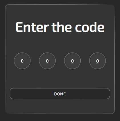](https://doc.redisage.com/uploads/images/gallery/2025-03/00Bimage.png) The default code is 0000. After logging in, a user can change it. The code settings are in the upper-right corner of the site, next to the help button. [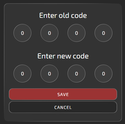](https://doc.redisage.com/uploads/images/gallery/2025-03/j3Vimage.png) ### Panels #### Overview The purpose of this panel is only to display data from different interfaces on a common chart. Output pins are to be controlled via individual interfaces pages. All of the below help images are also available on the site by clicking the question mark in the upper-right corner. [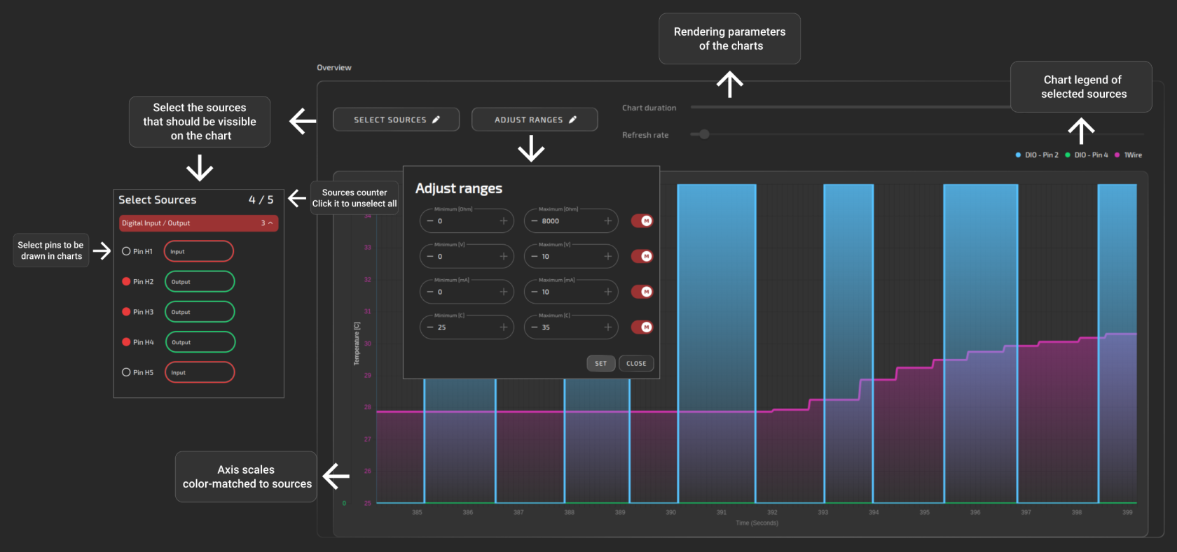](https://doc.redisage.com/uploads/images/gallery/2025-03/Da0image.png) #### Digital input [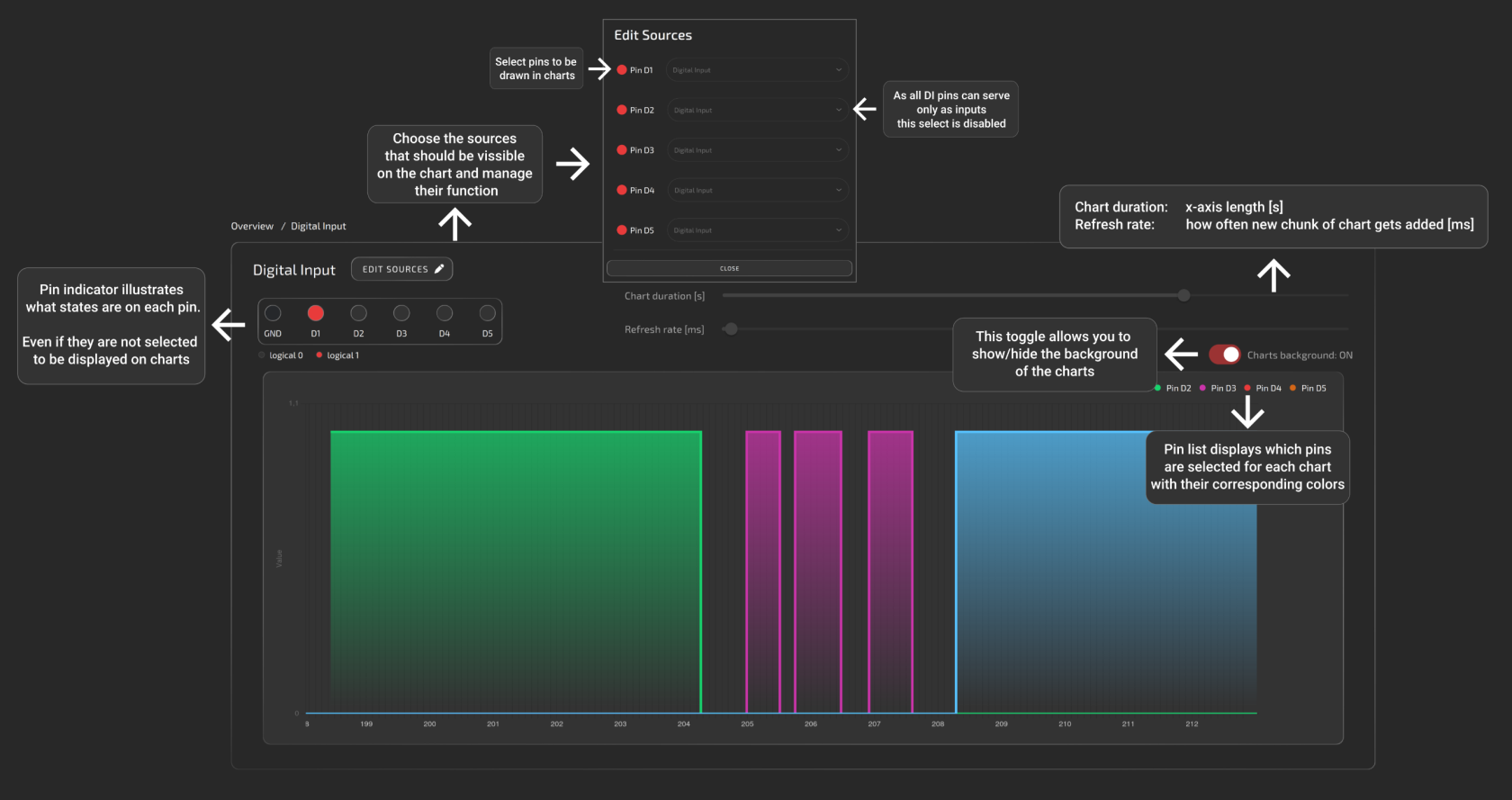](https://doc.redisage.com/uploads/images/gallery/2025-03/di.png) #### Digital input/output [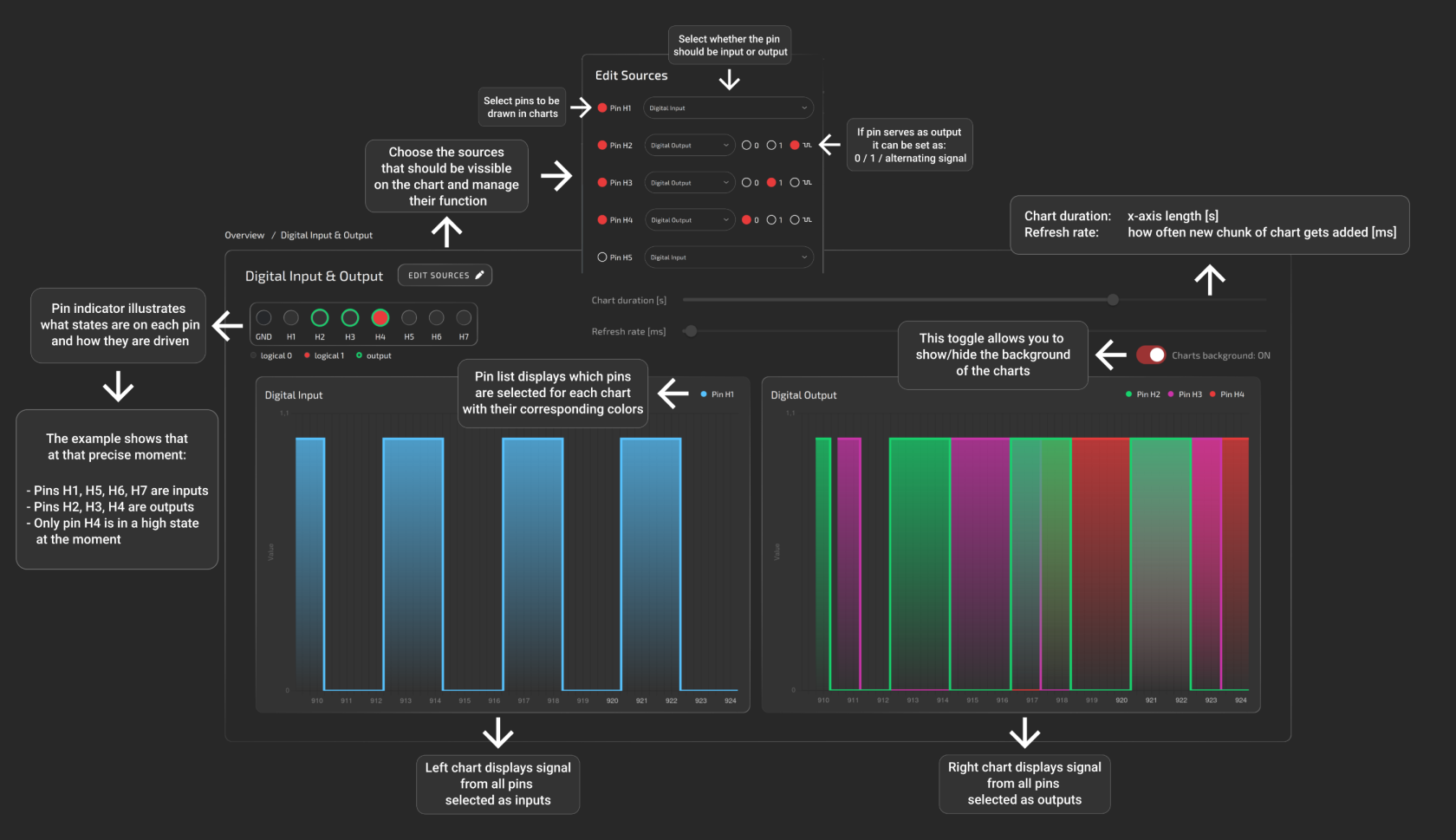](https://doc.redisage.com/uploads/images/gallery/2025-03/dio.png) #### Universal input/output [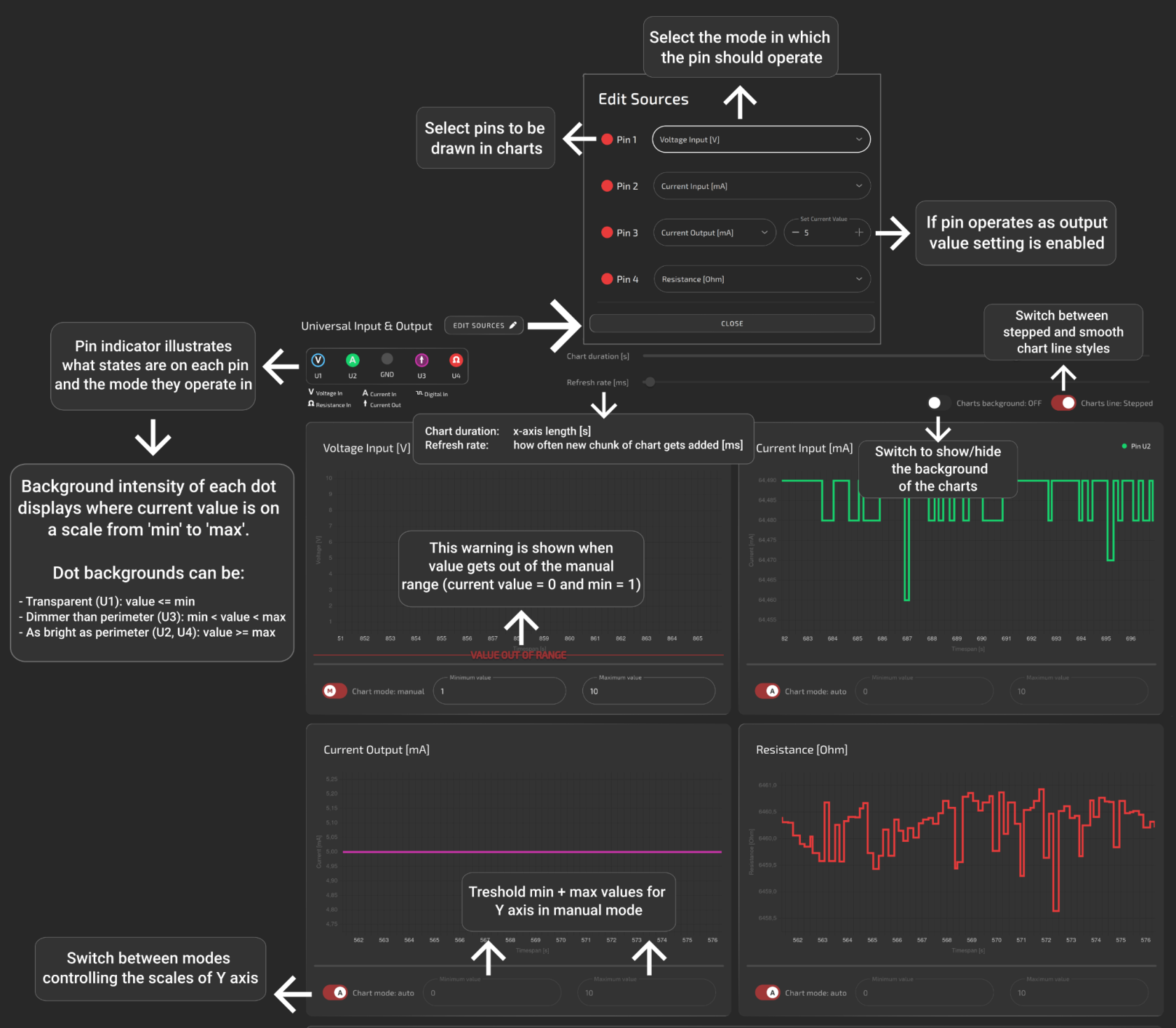](https://doc.redisage.com/uploads/images/gallery/2025-03/uio.png) #### Serial [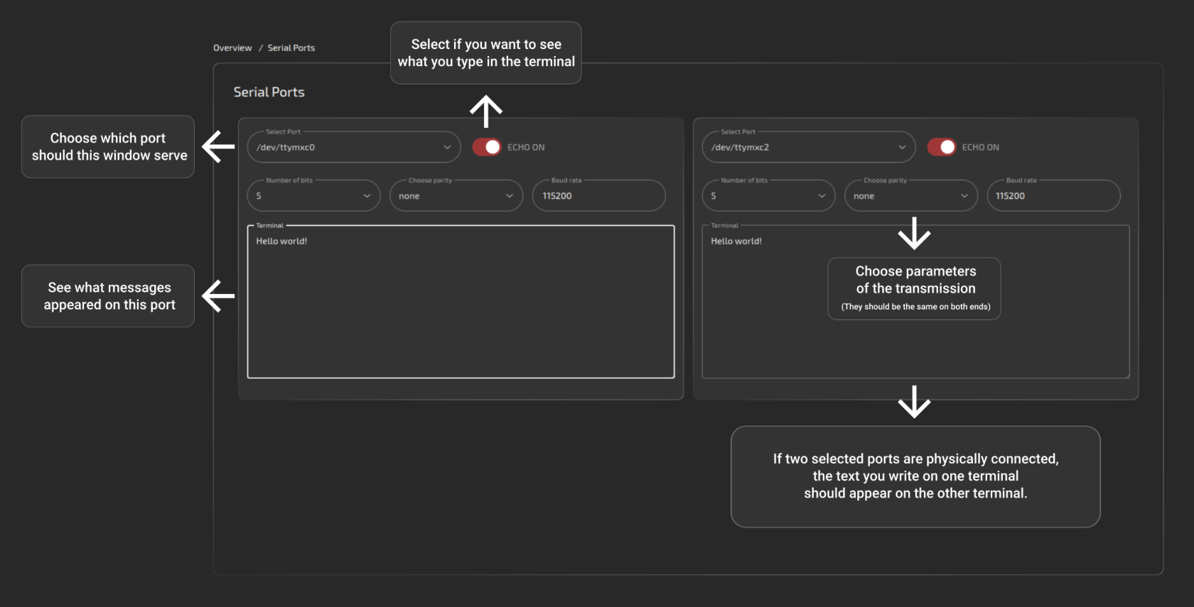](https://doc.redisage.com/uploads/images/gallery/2025-03/jMUimage.png) #### 1-Wire [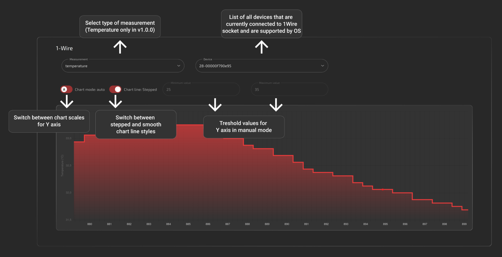](https://doc.redisage.com/uploads/images/gallery/2025-03/wire.png) #### Terminal This panel serves as a terminal emulator for basic communication with the device. It allows navigating through the directories, looking up logs or connected devices and much more. [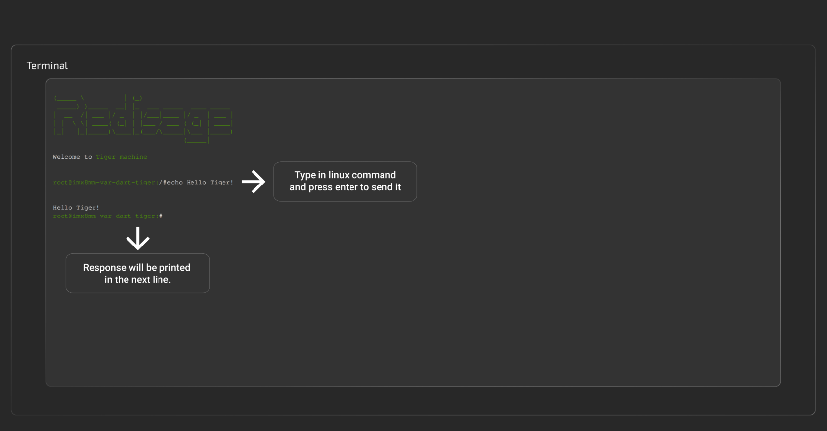](https://doc.redisage.com/uploads/images/gallery/2025-03/AlDimage.png) GitHub repository: soon. # Contact Us - [Main web page](https://redisage.com/) - [Facebook](https://www.facebook.com/Redisage/) - E-mail:| **Signal** | **Processor pin** | **Default function** |
| Chip select 0 | AD18 | SPI1\_CS0 |
| Chip select 1 | AG23 | SPI1\_CS1 |
| Master in slave out | A7 | SPI1\_MISO |
| Clock | D6 | SPI1\_SCLK |
| Master out slave in | B7 | SPI1\_MOSI |
| **Signal** | **Processor pin** | **Default function** |
| Chip select 0 | A6 | SPI2\_CS0 |
| Chip select 1 | AF12 | SPI2\_CS1 |
| Chip select 2 | AB19 | SPI2\_CS2 |
| Master in slave out | A8 | SPI2\_MISO |
| Clock | E6 | SPI2\_SCLK |
| Master out slave in | B8 | SPI2\_MOSI |
| **Signal** | **Processor pin** | **Default function** |
| Clock | D10 | I2C2\_SCL |
| Data | D9 | I2C2\_SDA |
| **Signal** | **Processor pin** | **Default function** |
| Clock | E10 | I2C3\_SCL |
| Data | F10 | I2C3\_SDA |
| **Signal** | **Processor pin** | **Default function** |
| Clock | D13 | I2C4\_SCL |
| Data | E13 | I2C4\_SDA |
| **Signal** | **Processor pin** | **Default function** |
| Receive (UART1 RX) | E14 | UART1\_RXD |
| Transmit (UART1 TX) | F13 | UART1\_TXD |
| **Signal** | **Processor pin** | **Default function** |
| Receive (UART2 RX) | X | UART2\_RXD |
| Transmit (UART2 TX) | X | UART2\_TXD |
| **Signal** | **Processor pin** | **Default function** |
| Receive (UART3 RX) | E18 | UART3\_RXD |
| Transmit (UART3 TX) | D18 | UART3\_TXD |
| **Signal** | **Processor pin** | **Default function** |
| Receive (UART4 RX) | F19 | UART4\_RXD |
| Transmit (UART4 TX) | F18 | UART4\_TXD |