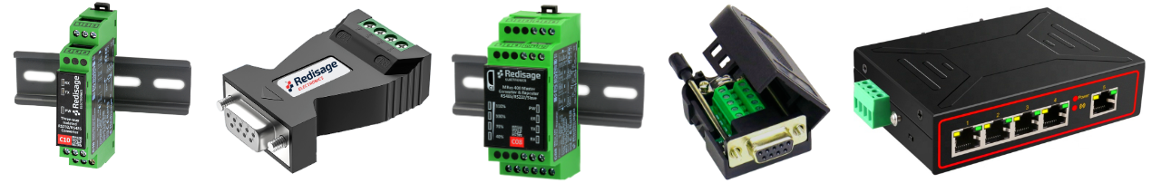
| **P10 P11 P12** [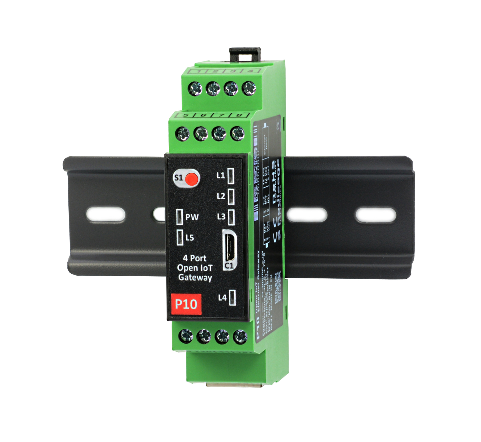](https://doc.redisage.com/uploads/images/gallery/2024-06/4Qcimage.png) | **Features** - Open IoT gateway - ESD protection for the RS485 data line - Power supply: +12 to +30 VDC - Transmission speed up to 115200 bps - 10/100 Mb/s Fast Ethernet standard - Tx, Rx and power LED indicators - RS485 embedded termination 120 ohm - Operating temperatures: -40°C to +75°C - DIN-rail mounting - Dimensions: 98x56.4x22.5 mm - 3 years warranty - Customization of OEM is welcomed |
|---|
| **Redisage PN** | **P10** | **P11** | **P12** | ||||
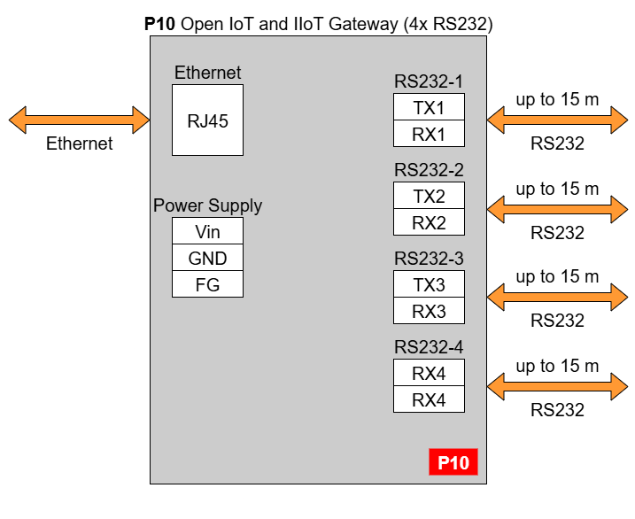
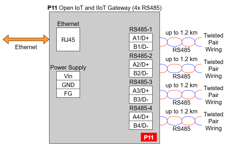
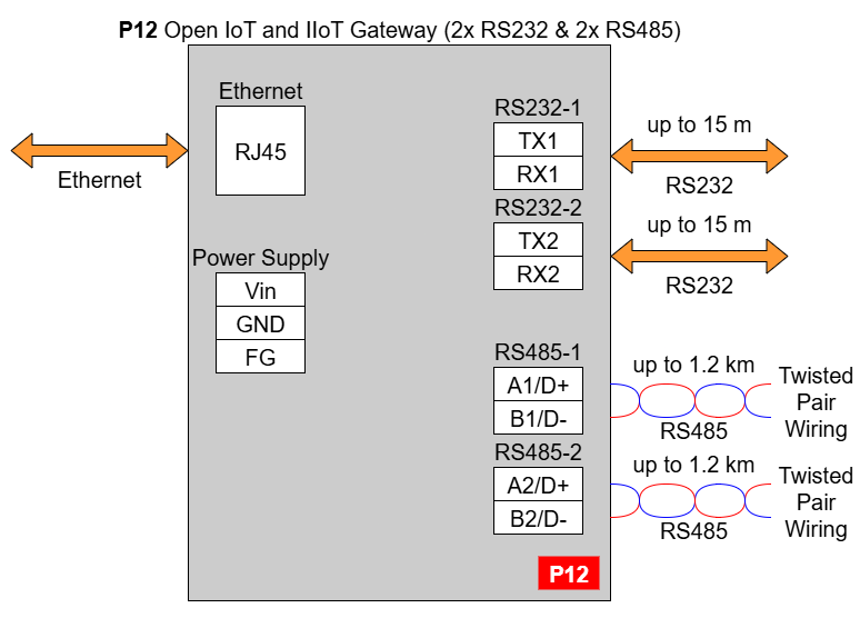
| Ports | RS232 | 4x | - | 2x | |||
| RS485 | - | 4x | 2x | ||||
| RS232/RS485 | - | - | - | ||||
| Microcontroller | STM32 | ||||||
| WiFi | N/A | ||||||
| Bluetooth | N/A | ||||||
| SMA socket connector for WiFi/BT antenna |  | ||||||
| Tactile switch |  | ||||||
| Power | Voltage | 12-30 VDC | |||||
| Power | < 1 W | ||||||
| Frame ground protection | yes | ||||||
| Baud rate | up to 115200 bps | ||||||
| LED indicators | power, link activity, programmable RGB | ||||||
| RS485 termination | 120 ohm manually enabled | ||||||
| Connector | RS232/RS485 | 8-pin terminal block max. 2.5 mm2 wire | |||||
| Power | 3-pin terminal block max. 2.5 mm2 wire | ||||||
| Ethernet | RJ45 | ||||||
| Transmission distance | RS485 | max. 1,200 m at 9.6 kbps; max. 400 m at 115.2 kbps (Belden 9841 2P twisted-pair cable, if different cables are used, the transmission distance may change) | |||||
| RS232 | max. 15 m at 115.2 kbps | ||||||
| Mounting and enclosure | DIN rail, plastic PA - UL 94 V0, black/green | ||||||
| Temperatures | -40°C to +75°C operating and storage | ||||||
| Humidity | 10 - 90% RH, non-condensing | ||||||
| ESD protection | ±4 kV contact discharge / ±8 kV air discharge | ||||||
| Certification | CE, RoHS, EMC, LVD | ||||||
| Norms | 61000-6-2 - Immunity standard for industrial environments 61000-6-4 - Emission standard for industrial environments | ||||||
| **P10** [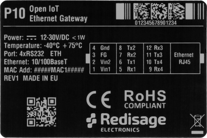](https://doc.redisage.com/uploads/images/gallery/2024-06/p10-name-plate-label-v1-1090.png) | **P11** [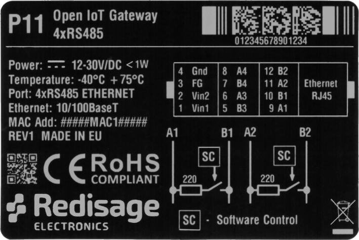](https://doc.redisage.com/uploads/images/gallery/2024-06/p11-name-plate-label-v1-1091.png) |
| **P12** [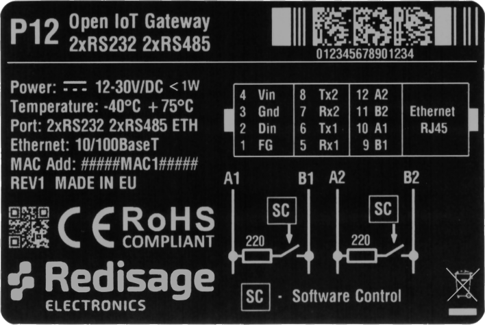](https://doc.redisage.com/uploads/images/gallery/2024-06/p12-name-plate-label-v1-1089.png) | |
| **Related information and links** | ||
| [Ordering information](https://redisage.com/en/delivery.html) | [Accessories](https://redisage.com/eng_m_Accessory-174.html) | [Similar products](https://redisage.com/search.php?text=+&sort=name&order=a) |
| **Features** | [](https://doc.redisage.com/uploads/images/gallery/2024-06/4Qcimage.png) |
|---|---|
| Open IoT gateway | |
| ESD protection for the RS485 data line | |
| Power supply: +12 to +30 VDC | |
| Transmission speed up to 115200 bps | |
| Tx, Rx and power LED indicators | |
| RS485 embedded termination 120 ohm | |
| Operating temperatures: -40°C to +75°C | |
| DIN-rail mounting | |
| Dimensions: 98x56.4x22.5 mm | |
| **3 years warranty** | |
| **Customization of OEM is welcomed** |
| **Gateways P10 - P12** | ||
| [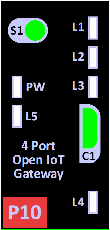](https://doc.redisage.com/uploads/images/gallery/2024-06/Llbimage.png) | ||
| **LED indicator** | **Color** | **Function** |
| PW | Blue | Power |
| L1 | Green | LED 1 |
| L2 | Green | LED 2 |
| L3 | Yellow | LED 3 |
| L4 | Red | LED 4 |
| L5 | Red | LED 5 |
RS232/RS485 ports depend on the device variant.
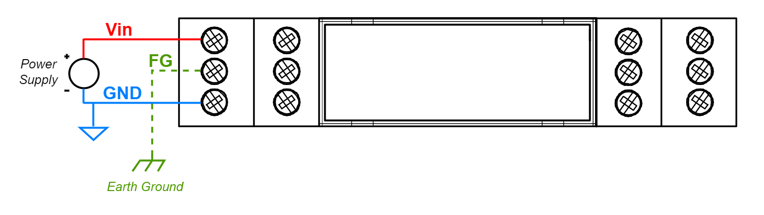
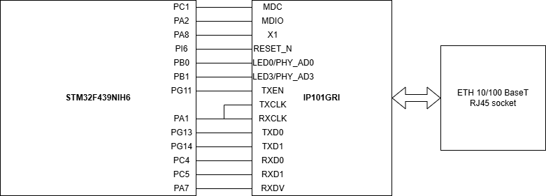
#### Ethernet To support the Ethernet network interface communication, the network adapter available in the kit must be installed on the module (pay attention to its correct installation). This interface is supported by the external IP101G physical layer which communicates with the STM32 microcontroller. [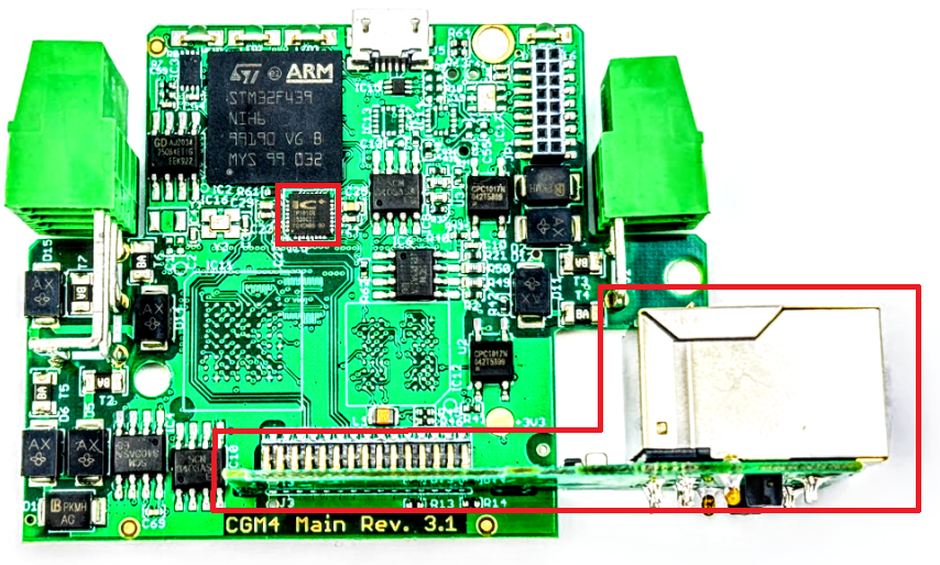](https://doc.redisage.com/uploads/images/gallery/2025-02/CEIimage.png) [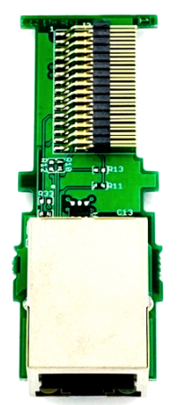](https://doc.redisage.com/uploads/images/gallery/2025-02/JUVimage.png) # Programming ## {{@264#bkmrk-open-iot-and-iiot-ga}} ### Install IDE & Programmer Download and install [STM32CubeIDE](https://www.st.com/en/development-tools/stm32cubeide.html#get-software) for ability to creating own programs. For device programming, you must install [STM32CubeProgrammer](https://www.st.com/en/development-tools/stm32cubeprog.html). Follow the instructions located on the producer's site. Software is available on Windows, Linux and macOS. Of course, there is a possibility of using other IDEs, but Cube is dedicated to STM32 MCUs and provides a lot of compatible libraries. ### Connect the programmer STM32 IoT and IIoT Gateways can be programmed only with the MCU producer's external hardware programmer - [ST LINK](https://www.st.com/en/development-tools/st-link-v2.html) - connected via the Tag-Connect connector to the board. After connecting it to the board and a PC, the device should be available in Device Manager as STM32 STLink in Universal Serial Bus devices. [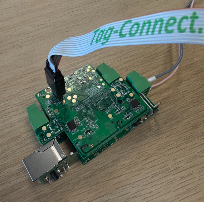](https://doc.redisage.com/uploads/images/gallery/2025-02/Y3mimage.png) ### Connect the power supply The gateway works with 12-30V DC power supplies. Make sure your supply is properly set. [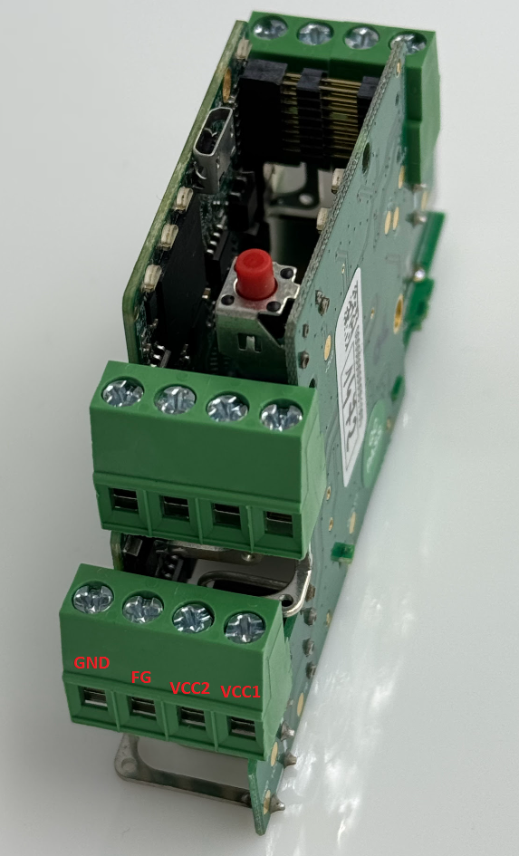](https://doc.redisage.com/uploads/images/gallery/2025-02/yKHimage.png) ### Create your own programs After all of the above steps are done, the device should be ready to be programmed. Example scripts and repositories are available [here](https://doc.redisage.com/books/stm32-open-iot-and-iiot-gateways/chapter/examples). ### Build, flash and monitor the device There are two options for building your program. ##### STM32CubeIDE [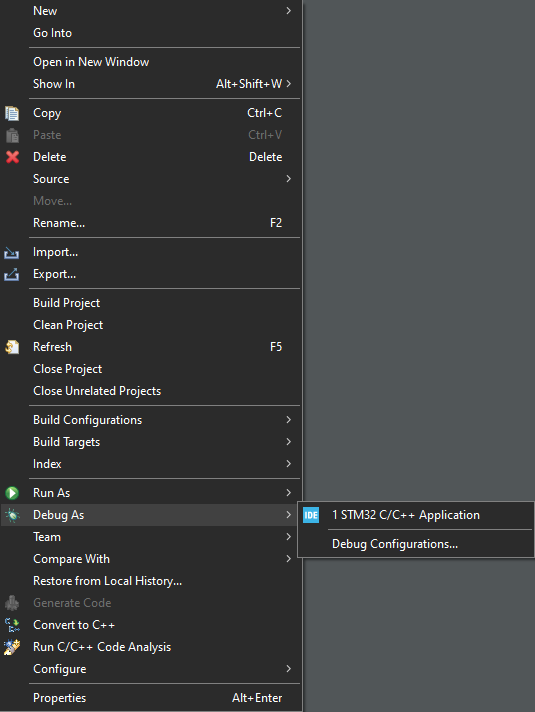](https://doc.redisage.com/uploads/images/gallery/2025-01/image.png) Right click on your project and choose Debug As -> STM32 C/C++ Application. It should generate the .elf file in the Debug folder in the project. ##### CMake The project can also be built in STM32CubeIDE via CMake. For more information and instructions check the producer's [instructions](https://www.st.com/resource/en/application_note/an5952-how-to-use-cmake-in-stm32cubeide-stmicroelectronics.pdf). #### Flash There are two ways to flash the device. ##### STM32CubeProgrammer It is the most recommended to use Programmer. Open the software and connect it to the ST-Link programmer. [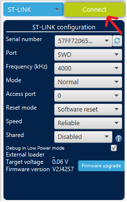](https://doc.redisage.com/uploads/images/gallery/2025-01/fCjimage.png) After successful connect you should see the device memory with addresses on the screen. Click on the down-arrow on the left side of the screen and browse for your file path. [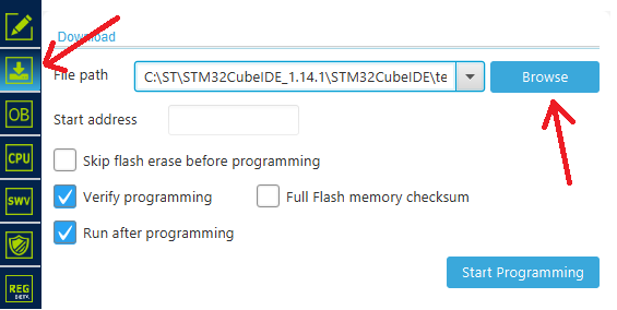](https://doc.redisage.com/uploads/images/gallery/2025-01/iWgimage.png) Find the .elf file (it should always be generated in the Debug folder in your project's path). [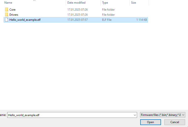](https://doc.redisage.com/uploads/images/gallery/2025-01/Ezsimage.png) Click "Open". [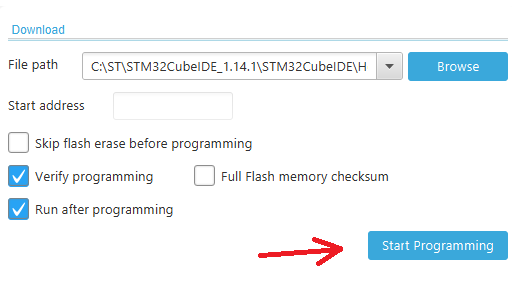](https://doc.redisage.com/uploads/images/gallery/2025-01/4gJimage.png) Click "Start Programming". If programming have been done successfully, you should see on the screen some messages in pop-up windows and Log console. [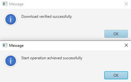](https://doc.redisage.com/uploads/images/gallery/2025-01/dUIimage.png) [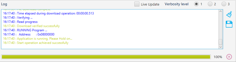](https://doc.redisage.com/uploads/images/gallery/2025-01/Vivimage.png) The Gateway has been programmed. ##### Flashing in IDE It is possible to flash your program directly from STM32CubeIDE. However, this method works only with some simple, small projects without using CMake. Just click on the  icon in the IDE, and after a few seconds, the device should be programmed. If it doesn't work, use the previous method. #### Monitoring You can connect the device to your computer using a console and Serial connection. To do so, you need two USB cables and a USB -> UART Converter (for example, [C37](https://redisage.com/usb-converter/c37-to-1x-uart-3v3-logic-ftdi)). If the connection is correct, the device will be visible as a USB Serial Port (COMx/ttyUSB). You can use any console terminal with the Serial option. The baudrate depends on USB UART settings in the project. # Pin Map ## {{@264#bkmrk-open-iot-and-iiot-ga}} ### CGM Rev. 3.1| Element | Connection |
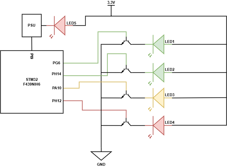
| **LED** | |
| Power LED | +3V3 |
| LED1 | PG6 |
| LED2 | PH14 |
| LED3 | PA10 |
| LED4 | PH12 |
| LED5 | PI9 |
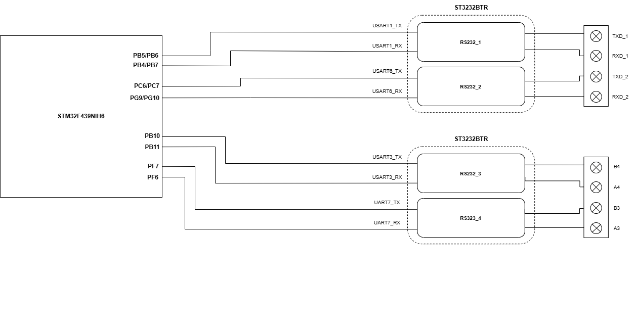
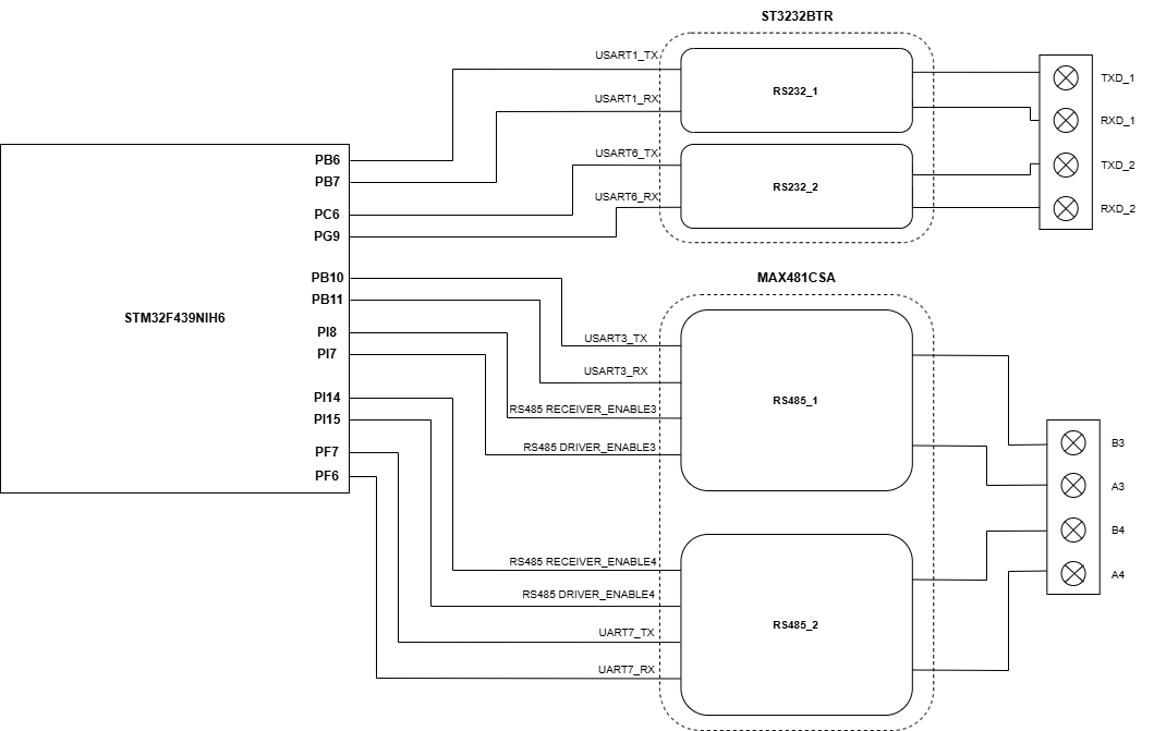
| **ST3232BTR\_1 UART RS232 Transceiver (P10 & P11)** | |
| T1\_IN | USART1\_TXD |
| T2\_IN | USART6\_TXD |
| T1\_OUT | TXD1 |
| T2\_OUT | TXD2 |
| R1\_IN | RXD1 |
| R2\_IN | RXD2 |
| R1\_OUT | USART1\_RXD |
| R2\_OUT | USART6\_RXD |
| V+ | C7 (100nF) |
| V- | C8 (100nF) |
| C1+ | C5 (100nF) |
| C1- | C5 (100nF) |
| C2+ | C6 (100nF) |
| C2- | C6 (100nF) |
| ESDA25-4BP6 ESD protection | |
| I/O\_1 | RXD2 |
| I/O\_2 | TXD1 |
| I/O\_3 | RXD1 |
| I/O\_4 | TXD2 |
| GND | FGC |
| **ST3232BTR\_2 UART RS232 Transceiver (P10)** | |
| T1\_IN | USART3\_TXD |
| T2\_IN | UART7\_TXD |
| T1\_OUT | B\_4 |
| T2\_OUT | B\_3 |
| R1\_IN | A\_4 |
| R2\_IN | A\_3 |
| R1\_OUT | USART3\_RXD |
| R2\_OUT | UART7\_RXD |
| V+ | C64 (100nF) |
| V- | C65 (100nF) |
| C1+ | C57 (100nF) |
| C1- | C57 (100nF) |
| C2+ | C50 (100nF) |
| C2- | C50 (100nF) |
| ESDA25-4BP6 ESD protection | |
| I/O\_1 | - |
| I/O\_2 | - |
| I/O\_3 | B\_4 |
| I/O\_4 | A\_4 |
| GND | FGC |
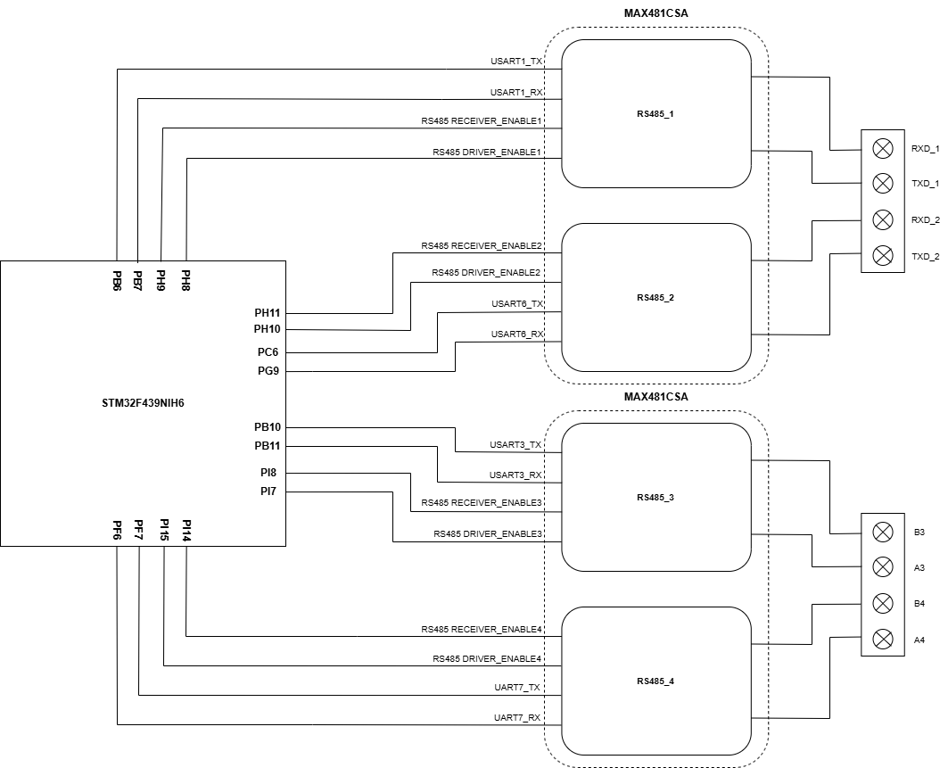
| **MAX481CSA\_1 UART RS485 Transceiver (P12)** | |
| DI | USART1\_TXD |
| DE | RS485\_DRIVER\_ENABLE1 |
| RE/ | RS485\_RECEIVER\_ENABLE1 |
| RO | USART1\_RXD |
| A | TXD1 |
| B | RXD1 |
| **MAX481CSA\_2 UART RS485 Transceiver (P12)** | |
| DI | USART6\_TXD |
| DE | RS485\_DRIVER\_ENABLE2 |
| RE/ | RS485\_RECEIVER\_ENABLE2 |
| RO | USART6\_RXD |
| A | TXD2 |
| B | RXD2 |
| **MAX481CSA\_3 UART RS485 Transceiver (P11 & P12)** | |
| DI | USART3\_TXD |
| DE | RS485\_DRIVER\_ENABLE3 |
| RE/ | RS485\_RECEIVER\_ENABLE3 |
| RO | USART3\_RXD |
| A | A\_3 |
| B | B\_3 |
| **MAX481CSA\_4 UART RS485 Transceiver (P11 & P12)** | |
| DI | UART7\_TXD |
| DE | RS485\_DRIVER\_ENABLE4 |
| RE/ | RS485\_RECEIVER\_ENABLE4 |
| RO | UART7\_RXD |
| A | A\_4 |
| B | B\_4 |
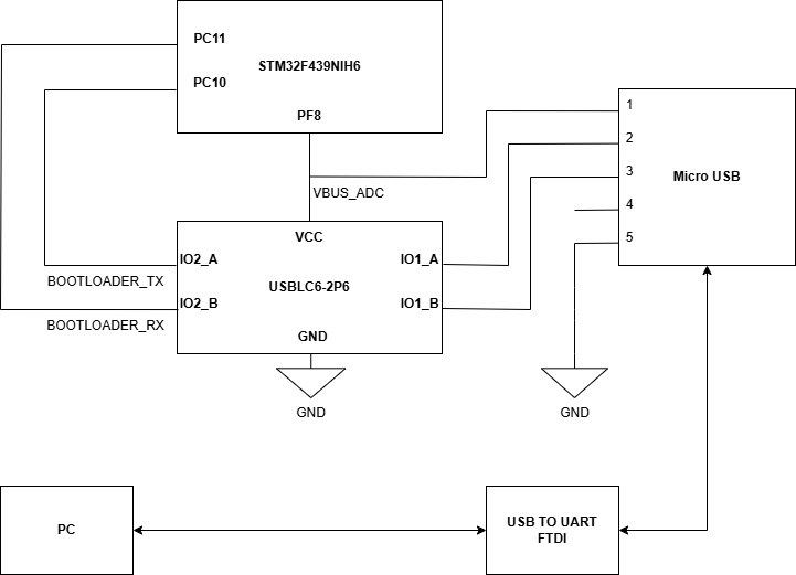
| **USBLC6-2P6 ESD protection** | |
| VCC | VBUS\_ADC, MICROUSB\_B\_U254-051T-4BH83-F1S (PIN1) |
| GND | GND |
| IO1\_A | MICROUSB\_B\_U254-051T-4BH83-F1S (PIN2) |
| IO2\_A | MICROUSB\_B\_U254-051T-4BH83-F1S (PIN3) |
| IO1\_B | BOOTLOADER\_TX |
| IO2\_B | BOOTLOADER\_RX |
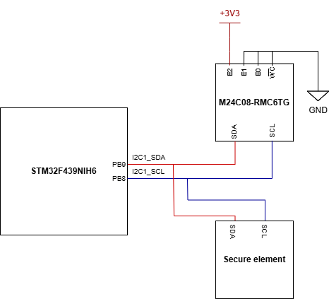
| **Serial EEPROM M24C08-RMC6TG** | |
| E0 | GND |
| E1 | GND |
| E2 | +3V3 |
| VSS | GND |
| VCC | +3V3 |
| WC/ | GND |
| SCL | I2C1\_SCL |
| SDA | I2C1\_SDA |
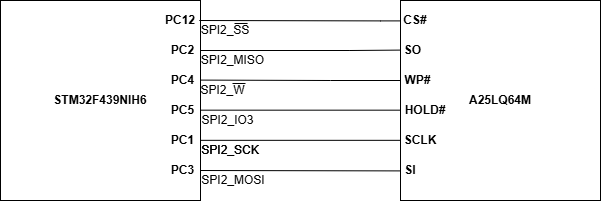
| **Serial Flash A25LQ64M** | |
| CS# | SPI2\_SS |
| SO | SPI2\_MISO |
| WP# | SPI2\_W |
| VSS | GND |
| VCC | +3V3 |
| HOLD# | SPI2\_IO3 |
| SCLK | SPI2\_SCK |
| SI | SPI2\_MOSI |
| **IP101GRI ETHERNET PHY transceivers** | |
| MDC | ETH\_MDC |
| MDIO | ETH\_MDIO |
| MDI\_TP | TXD+ |
| MDI\_TN | TXD- |
| MDI\_RP | RXD+ |
| MDI\_RN | RXD- |
| X2 | - |
| X1 | ETH\_MCO |
| RESET\_N | ETH\_RESET\_N |
| ISET | ETH\_ISET |
| LED0/PHY\_AD0 | ETH\_LED0/PHY\_AD0 |
| LED3/PHY\_AD3 | ETH\_LED3/PHY\_AD3 |
| TEST\_ON | - |
| REGOUT | C23 (100 nF), C29 (10 uF) |
| VDDIO | +3V3 |
| AVDD33 | +3V3 |
| GND | GND |
| TXEN | ETH\_TX\_EN |
| TXER/FXSD | - |
| TXCLK/50M\_CLKI | ETH\_RMII\_REF\_CLK |
| TXD0 | ETH\_TXD0 |
| TXD1 | ETH\_TXD1 |
| TXD2 | - |
| TXD3 | - |
| RXDV/CRS\_DV/FX\_HEN | ETH\_RXDV/CRS\_DV |
| RXCLK/50M\_CLKO | - |
| RXD0 | ETH\_RXD0 |
| RXD1 | ETH\_RXD1 |
| RXD2 | - |
| RXD3 | - |
| RXER/INTR\_32 | - |
| COL/RMII | ETH\_COL/RMII |
| CRS/LEDMOD | - |
| **STM32 F439NIH6** | |
| PA0 | - |
| PA1 | ETH\_RMII\_REF\_CLK |
| PA2 | ETH\_MDIO |
| PA3 | - |
| PA4 | - |
| PA5 | - |
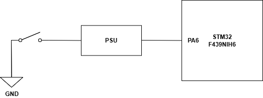
| PA6 | SWITCH |
| PA7 | ETH\_RXDV/CRS\_DV |
| PA8 | ETH\_MCO |
| PA9 | BUZZER\_PWM |
| PA10 | LED\_A3 |
| PA11 | USB\_DM BOOTLOADER\_RX |
| PA12 | USB\_DP BOOTLOADER\_TX |
| PA13 | JTMS |
| PA14 | JTCK |
| PA15 | CONF2 |
| PB0 | ETH\_LED0/PHY\_AD0 |
| PB1 | ETH\_LED3/PHY\_AD3 |
| PB2 | BOOT1 |
| PB3 | SW0 |
| PB4 | USART1\_RXD |
| PB5 | USART1\_TXD |
| PB6 | USART1\_TXD |
| PB7 | USART1\_RXD |
| PB8 | I2C1\_SCL |
| PB9 | I2C1\_SDA |
| PB10 | USART3\_TXD |
| PB11 | USART3\_RXD |
| PB12 | USART3\_RXD |
| PB13 | USART3\_TXD |
| PB14 | - |
| PB15 | - |
| PC0 | SD\_NWE |
| PC1 | ETH\_MDC |
| PC2 | - |
| PC3 | - |
| PC4 | ETH\_RXD0 |
| PC5 | ETH\_RXD1 |
| PC6 | USART6\_TXD |
| PC7 | USART6\_TXD |
| PC8 | CONF4 |
| PC9 | CONF1 |
| PC10 | BOOTLOADER\_TX |
| PC11 | BOOTLOADER\_RX |
| PC12 | CONF3 |
| PC13 | RTC\_AF1 |
| PC14 | OSC32\_IN |
| PC15 | OSC32\_OUT |
| PD0 | D2 |
| PD1 | D3 |
| PD2 | CONF6 |
| PD3 | - |
| PD4 | NOR\_NOE |
| PD5 | NOR\_NWE |
| PD6 | NOR\_NWAIT |
| PD7 | NOR\_NE1 |
| PD8 | D13 |
| PD9 | D14 |
| PD10 | D15 |
| PD11 | A16 |
| PD12 | A17 |
| PD13 | A18 |
| PD14 | D0 |
| PD15 | D1 |
| PE0 | SD\_LDOM |
| PE1 | SD\_UDOM |
| PE2 | - |
| PE3 | A19 |
| PE4 | A20 |
| PE5 | A21 |
| PE6 | - |
| PE7 | D4 |
| PE8 | D5 |
| PE9 | D6 |
| PE10 | D7 |
| PE11 | D8 |
| PE12 | D9 |
| PE13 | D10 |
| PE14 | D11 |
| PE15 | D12 |
| PF0 | A0 |
| PF1 | A1 |
| PF2 | A2 |
| PF3 | A3 |
| PF4 | A4 |
| PF5 | A5 |
| PF6 | UART7\_RXD |
| PF7 | UART7\_TXD |
| PF8 | VBUS\_ADC |
| PF9 | L2 |
| PF10 | L1 |
| PF11 | SD\_NDRAS |
| PF12 | A6 |
| PF13 | A7 |
| PF14 | A8 |
| PF15 | A9 |
| PG0 | A10 |
| PG1 | A11 |
| PG2 | A12 |
| PG3 | A13 |
| PG4 | A14 |
| PG5 | A15 |
| PG6 | LED\_A1 |
| PG7 | DIP\_SWITCH |
| PG8 | SD\_CLK |
| PG9 | USART6\_RXD |
| PG10 | USART6\_RXD |
| PG11 | ETH\_TXEN |
| PG12 | - |
| PG13 | ETH\_TXD0 |
| PG14 | ETH\_TXD1 |
| PG15 | SD\_NCAS |
| PH0 | OSC+IN |
| PH1 | OSC\_OUT |
| PH2 | SD\_CKE0 |
| PH3 | SD\_NE0 |
| PH4 | I2C2\_SCL |
| PH5 | I2C2\_SDA |
| PH6 | - |
| PH7 | - |
| PH8 | RS485\_DRIVER\_ENABLE1 |
| PH9 | RS485\_RECEIVER\_ENABLE1 |
| PH10 | RS485\_DRIVER\_ENABLE2 |
| PH11 | RS485\_RECEIVER\_ENABLE2 |
| PH12 | LED\_A4 |
| PH13 | - |
| PH14 | LED\_A2 |
| PH15 | CONF5 |
| PI0 | WP#//ACC |
| PI1 | SPI2\_SCK |
| PI2 | SPI2\_MISO |
| PI3 | SPI2\_MOSI |
| PI4 | SPI2\_W |
| PI5 | SPI2\_IO3 |
| PI6 | ETH\_RST |
| PI7 | RS485\_DRIVER\_ENABLE3 |
| PI8 | RS485\_RECEIVER\_ENABLE3 |
| PI9 | LED\_5 |
| PI10 | RS485\_TERMINATION\_ENABLE4 |
| PI11 | RS485\_TERMINATION\_ENABLE3 |
| PI12 | SPI2\_SS |
| PI13 | - |
| PI14 | RS485\_RECEIVER\_ENABLE4 |
| PI15 | RS485\_DRIVER\_ENABLE4 |
| Element | Connection |
| **HTS221** | |
| VDD | +3V3 |
| CS | +3V3 |
| GND | GND |
| SCL/SPC | I2C2\_SCL |
| SDA/SDI/SDO | I2C2\_SDA |
| DRDY | - |
| **LIS3DH** | |
| VDD\_IO | +3V3 |
| NC | - |
| NC | - |
| SCL/SPC | I2C2\_SCL |
| GND | GND |
| SDA/SDI/SDO | I2C2\_SDA |
| SDO/SAO | - |
| CS | +3V3 |
| ADC1 | - |
| ADC2 | - |
| VDD | +3V3 |
| ADC3 | - |
| GND | GND |
| INT1 | - |
| RES | GND |
| INT2 | - |
| **LSM6DS33** | |
| GND, GND, RES, RES, RES, RES | GND |
| INT1 | - |
| INT2 | - |
| VDDIO | +3V3 |
| SCL | I2C2\_SCL |
| SDA | I2C2\_SDA |
| SDO | - |
| CS | +3V3 |
| NC | - |
| RES | GND |
| VDD | +3V3 |
| **SI7006-A20/SI7020-A20** | |
| SDA | I2C2\_SDA |
| SCL | I2C2\_SCL |
| GND | GND |
| VDD | +3V3 |
| DNC1 | - |
| DNC2 | - |
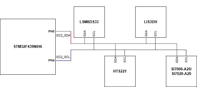
The presented devices are not included in the Open IoT Gateway.
# Examples [GitHub](https://github.com/Redisage/STM32_Open_IoT_and_IIoT_Gateways_examples) # Hello World ## {{@264#bkmrk-open-iot-and-iiot-ga}} Link to repositories: - [C](https://github.com/Redisage/STM32_Open_IoT_and_IIoT_Gateways_examples/tree/main/Hello_world_example) This example uses UART4 in the MCU which is reserved for the USB UART communication. A simple string is printed on the console and then the device restarts after 10 seconds of countdown. Use 115200 baudrate. [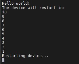](https://doc.redisage.com/uploads/images/gallery/2025-01/KCnimage.png) # LED ## {{@264#bkmrk-open-iot-and-iiot-ga}} Link to repositories: - [C](https://github.com/Redisage/STM32_Open_IoT_and_IIoT_Gateways_examples/tree/main/LED_example) A simple blinking LED example intended for the Open IoT Gateway. Lighting LED will be changed every 1 second from LED1 to LED5. # Switch ## {{@264#bkmrk-open-iot-and-iiot-ga}} Link to repositories: - [C](https://github.com/Redisage/STM32_Open_IoT_and_IIoT_Gateways_examples/tree/main/Button_example) Simple tactile switch example intended for the Open IoT Gateway. After flash, connect device to a PC and open port in Console Terminal. The information about the switch pressed state will be displayed in the console as shown below. [](https://doc.redisage.com/uploads/images/gallery/2025-01/v4Aimage.png) # RS232/RS485 ## {{@264#bkmrk-open-iot-and-iiot-ga}} Link to repositories: - [C](https://github.com/Redisage/STM32_Open_IoT_and_IIoT_Gateways_examples/tree/main/RS_Example) This script tests internal communication between serial ports with the possible lowest (2400) and highest (115200) baudrate. For this example, connect each port's transceiver with the receiver: [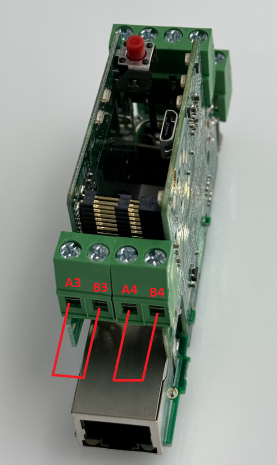](https://doc.redisage.com/uploads/images/gallery/2025-02/image.png)[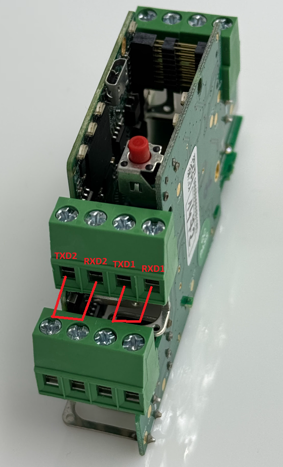](https://doc.redisage.com/uploads/images/gallery/2025-02/jkIimage.png) Default settings: - baud rate: 115200 - data bits: 8 - parity bits: 0 - stop bits: 1 - receiver timeout: 3s If the connection is right, you should see the messages shown below for each U(S)ART: [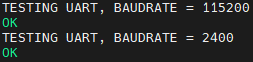](https://doc.redisage.com/uploads/images/gallery/2025-01/sktimage.png) If something goes wrong with the connection, you will see the message for a specific port like below: [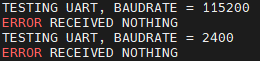](https://doc.redisage.com/uploads/images/gallery/2025-01/c10image.png) # Ethernet ## {{@264#bkmrk-open-iot-and-iiot-ga}} Link to repositories: - [C](https://github.com/Redisage/STM32_Open_IoT_and_IIoT_Gateways_examples/tree/main/Ethernet_IP_example) [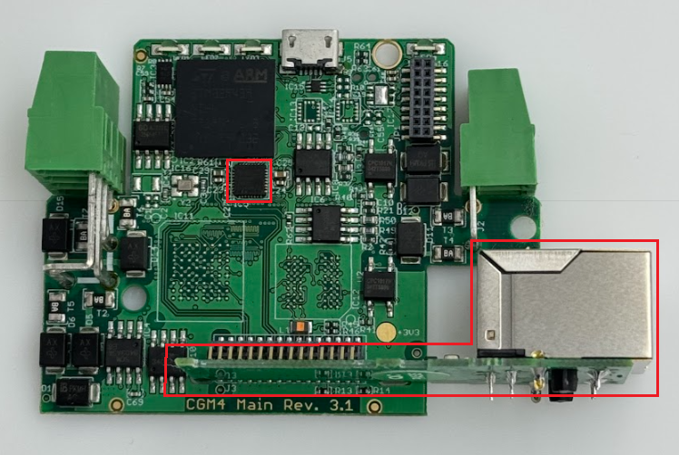](https://doc.redisage.com/uploads/images/gallery/2025-02/Wp0image.png) This example allows you to check the Gateway's IP address. Connect the device via USB/UART converter and choose correct COM/ttyUSB port. Remember to connect the IoT Gateway to the network using an Ethernet cable. Type in terminal "ipconfig". If your network connection works properly, IP address will be displayed as below: [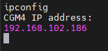](https://doc.redisage.com/uploads/images/gallery/2025-01/dJBimage.png) # I2C scanner ## {{@264#bkmrk-open-iot-and-iiot-ga}} Link to repositories: - [C](https://github.com/Redisage/STM32_Open_IoT_and_IIoT_Gateways_examples/tree/main/i2c_scanner) A simple program for scanning and displaying addresses of connected devices via I2C bus. [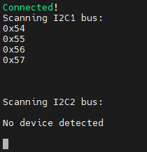](https://doc.redisage.com/uploads/images/gallery/2025-01/WTOimage.png) # Contact Us - [Main web page](https://redisage.com/) - [Facebook](https://www.facebook.com/Redisage/) - E-mail:| **Redisage PN** | **P10** | **P11** | **P12** | ||||
| Ports | RS232 | 4x | - | 2x | |||
| RS485 | - | 4x | 2x | ||||
| RS232/RS485 | - | - | - | ||||
| Microcontroller | STM32 | ||||||
| WiFi | N/A | ||||||
| Bluetooth | N/A | ||||||
| SMA socket connector for WiFi/BT antenna |  | ||||||
| Tactile switch |  | ||||||
| Power | Voltage | 12-30 VDC | |||||
| Power | < 1 W | ||||||
| Frame ground protection | yes | ||||||
| Baud rate | up to 115200 bps | ||||||
| LED indicators | power, link activity, programmable RGB | ||||||
| RS485 termination | 120 ohm manually enabled | ||||||
| Connector | RS232/RS485 | 8-pin terminal block max. 2.5 mm2 wire | |||||
| Power | 3-pin terminal block max. 2.5 mm2 wire | ||||||
| Ethernet | RJ45 | ||||||
| Transmission distance | RS485 | max. 1,200 m at 9.6 kbps; max. 400 m at 115.2 kbps (Belden 9841 2P twisted-pair cable, if different cables are used, the transmission distance may change) | |||||
| RS232 | max. 15 m at 115.2 kbps | ||||||
| Mounting and enclosure | DIN rail, plastic PA - UL 94 V0, black/green | ||||||
| Temperatures | -40°C to +75°C operating and storage | ||||||
| Humidity | 10 - 90% RH, non-condensing | ||||||
| ESD protection | ±4 kV contact discharge / ±8 kV air discharge | ||||||
| Certification | CE, RoHS, EMC, LVD | ||||||
| Norms | 61000-6-2 - Immunity standard for industrial environments 61000-6-4 - Emission standard for industrial environments | ||||||
| **P10** [](https://doc.redisage.com/uploads/images/gallery/2024-06/p10-name-plate-label-v1-1090.png) | **P11** [](https://doc.redisage.com/uploads/images/gallery/2024-06/p11-name-plate-label-v1-1091.png) |
| **P12** [](https://doc.redisage.com/uploads/images/gallery/2024-06/p12-name-plate-label-v1-1089.png) | |