STM32 Open IoT and IIoT Gateways
P10 - P12 Open IoT and IIoT Gateways documentation
Data Sheet
STM32 Open IoT and IIoT Gateways (P10 - P12)
Open IoT Gateway is also called as a PAC (Programmable Automation Controller). PAC products combine the functionality and openness of PC, the reliability of a programmable logic unit like PLC and the intelligence of I/O modules with flexible software tools for a wide range of applications from data acquisition, process control, motion control to energy and building management.
Our PAC family includes FreeRTOS PACs for different requirements in OS, CPU and development platforms.
The P10 - P12 gateways are based on STM32 ARM Cortex-M4.
|
P10 P11 P12
|
Features
|
|---|
Specifications
|
Redisage PN |
P10 |
P11 |
P12 |
||||
|
Ports |
RS232 |
4x |
- |
2x |
|||
|
RS485 |
- |
4x |
2x |
||||
|
RS232/RS485 |
- |
- |
- |
||||
|
Microcontroller |
STM32 |
||||||
|
WiFi |
N/A | ||||||
|
Bluetooth |
N/A | ||||||
|
SMA socket connector for WiFi/BT antenna |
|||||||
|
Tactile switch |
|||||||
|
Power |
Voltage |
12-30 VDC |
|||||
|
Power |
< 1 W |
||||||
|
Frame ground protection |
yes |
||||||
|
Baud rate |
up to 115200 bps |
||||||
|
LED indicators |
power, link activity, programmable RGB |
||||||
|
RS485 termination |
120 ohm manually enabled |
||||||
|
Connector |
RS232/RS485 |
8-pin terminal block max. 2.5 mm2 wire |
|||||
|
Power |
3-pin terminal block max. 2.5 mm2 wire |
||||||
|
Ethernet |
RJ45 |
||||||
|
Transmission |
RS485 |
max. 1,200 m at 9.6 kbps; max. 400 m at 115.2 kbps |
|||||
|
RS232 |
max. 15 m at 115.2 kbps |
||||||
|
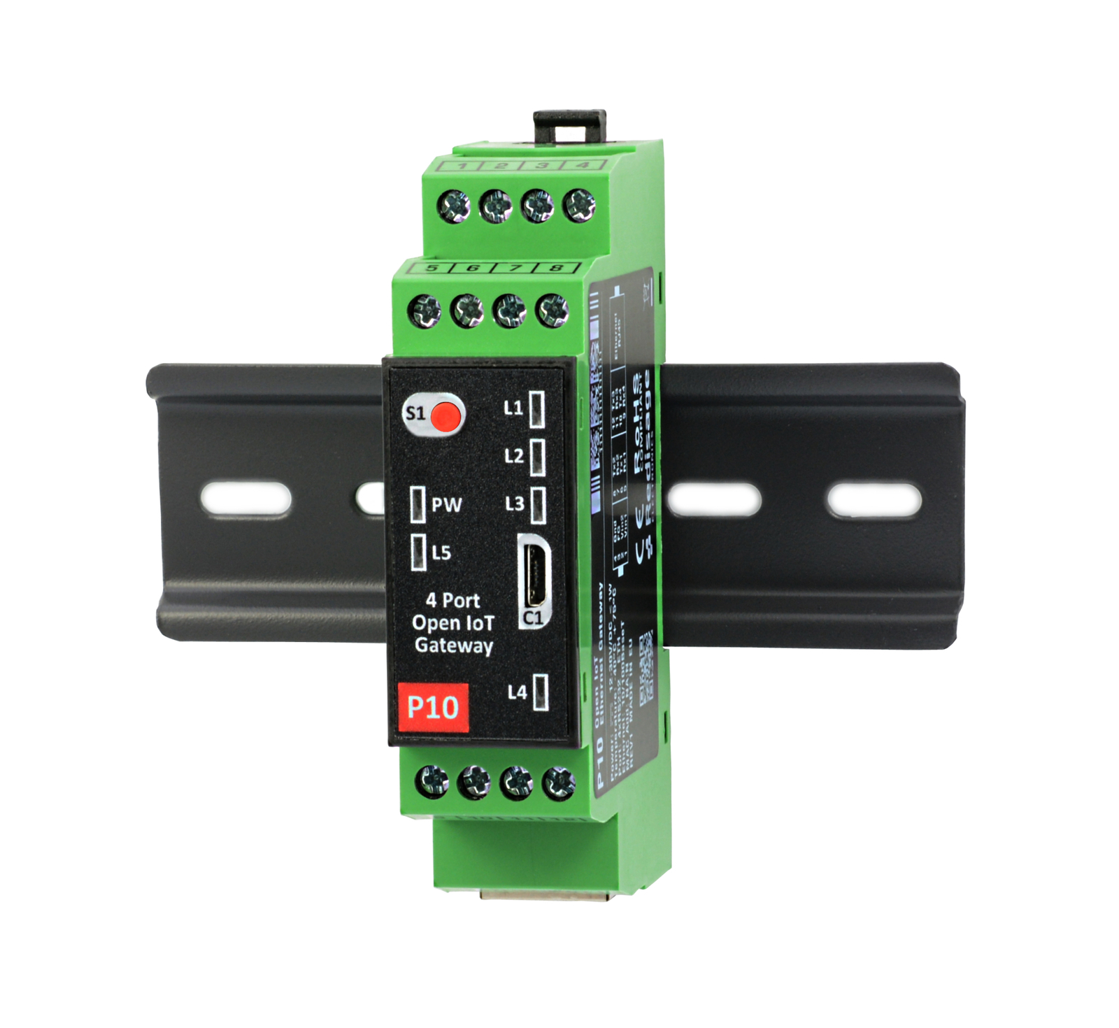
Mounting and enclosure |
DIN rail, plastic PA - UL 94 V0, black/green |
||||||
|
Temperatures |
-40°C to +75°C operating and storage |
||||||
|
Humidity |
10 - 90% RH, non-condensing |
||||||
|
ESD protection |
±4 kV contact discharge / ±8 kV air discharge |
||||||
|
Certification |
CE, RoHS, EMC, LVD |
||||||
|
Norms |
61000-6-2 - Immunity standard for industrial environments 61000-6-4 - Emission standard for industrial environments |
||||||
Variants
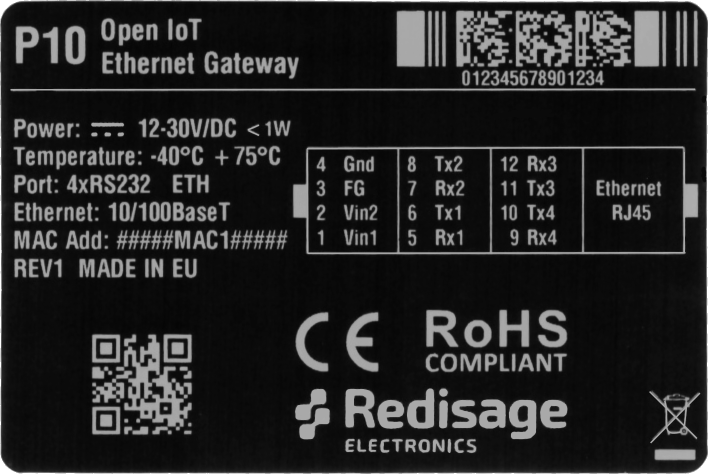
P10 - Open IoT and IIoT Gateway 4x RS232

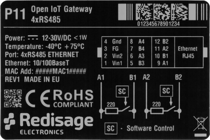
P11 - Open IoT and IIoT Gateway 4x RS485

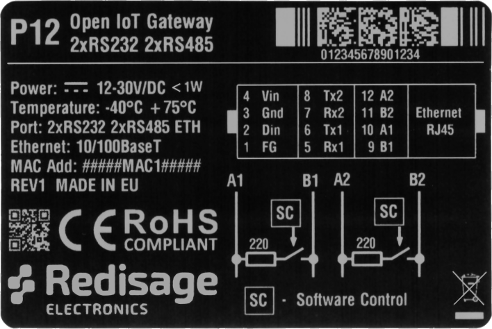
P12 - Open IoT and IIoT Gateway 2x RS232 & 2x RS485

Frame ground FG
Electronic circuits are constantly prone to electrostatic discharge ESD. Redisage Electronics modules feature a design for the frame ground terminal block FG. The frame ground provides a path for bypassing ESD, which provides enhanced static protection ESD abilities and ensures the module is more reliable. Connecting FG terminal block to the earth ground will bypass the ESD disturbances outside the device so will provide a better level of protection against ESD.
Frame Ground FG connection reference drawing is provided below.

If earth ground is not available FG can be left floating or it can be connected with the power supply GND.
Pin assignments
|
P10
|
P11
|
|
P12
|
|
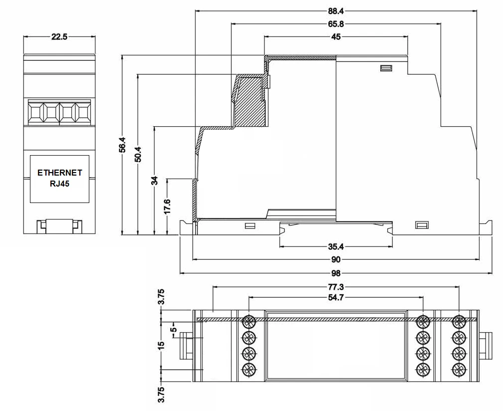
Enclosure dimensions
2U Module Enclosure
98 x 22.5 x 56.4
Units: mm
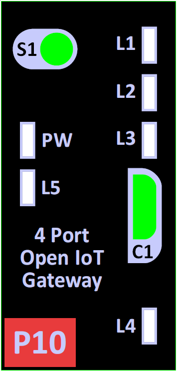
LED indicators
- PW LED Blue - Power
- L1 - LED 1
- L2 - LED 2
- L3 - LED 3
- L4 - LED 4
- L5 - LED 5
Additional notes
| Related information and links |
||
| Ordering information | Accessories | Similar products |
Products family sample photo

DISCLAMER NOTES
ALL PRODUCT, PRODUCT SPECIFICATIONS AND DATA ARE SUBJECT TO CHANGE WITHOUT NOTICE TO IMPROVE RELIABILITY, FUNCTION OR DESIGN OR OTHERWISE.
Datasheet-ID:
SR-D
User Manual
Introduction
STM32 Open IoT and IIoT Gateways (P10 - P12)
Open IoT Gateway is also called as a PAC (Programmable Automation Controller). PAC products combine the functionality and openness of PC, the reliability of a programmable logic unit like PLC and the intelligence of I/O modules with flexible software tools for a wide range of applications from data acquisition, process control, motion control to energy and building management.
Our PAC family includes FreeRTOS PACs for different requirements in OS, CPU and development platforms.
The P10 - P12 gateways are based on STM32 ARM Cortex-M4.
If you want to get started, make sure you have complete set of:
- Tag-connect cable
- Tag-connect retaining clip board (optional)
- Open IoT and IIoT Gateway
- USB Programmer
- ST-LINK programmer
Hardware
STM32 Open IoT and IIoT Gateways (P10 - P12)
Features
|
Features |
|
|---|---|
|
Open IoT gateway |
|
|
ESD protection for the RS485 data line |
|
|
Power supply: +12 to +30 VDC |
|
|
Transmission speed up to 115200 bps |
|
|
Tx, Rx and power LED indicators |
|
|
RS485 embedded termination 120 ohm |
|
|
Operating temperatures: -40°C to +75°C |
|
|
DIN-rail mounting |
|
|
Dimensions: 98x56.4x22.5 mm |
|
|
3 years warranty |
|
|
Customization of OEM is welcomed |
Frame ground FG
Electronic circuits are constantly prone to electrostatic discharge ESD. Redisage Electronics modules feature a design for the frame ground terminal block FG. The frame ground provides a path for bypassing ESD, which provides enhanced static protection ESD abilities and ensures the module is more reliable. Connecting FG terminal block to the earth ground will bypass the ESD disturbances outside the device so will provide a better level of protection against ESD.
Frame Ground FG connection reference drawing is provided below.
If earth ground is not available FG can be left floating or it can be connected with the power supply GND.
Specifications
|
Redisage PN |
P10 |
P11 |
P12 |
||||
|
Ports |
RS232 |
4x |
- |
2x |
|||
|
RS485 |
- |
4x |
2x |
||||
|
RS232/RS485 |
- |
- |
- |
||||
|
Microcontroller |
STM32 |
||||||
|
WiFi |
N/A | ||||||
|
Bluetooth |
N/A | ||||||
|
SMA socket connector for WiFi/BT antenna |
|||||||
|
Tactile switch |
|||||||
|
Power |
Voltage |
12-30 VDC |
|||||
|
Power |
< 1 W |
||||||
|
Frame ground protection |
yes |
||||||
|
Baud rate |
up to 115200 bps |
||||||
|
LED indicators |
power, link activity, programmable RGB |
||||||
|
RS485 termination |
120 ohm manually enabled |
||||||
|
Connector |
RS232/RS485 |
8-pin terminal block max. 2.5 mm2 wire |
|||||
|
Power |
3-pin terminal block max. 2.5 mm2 wire |
||||||
|
Ethernet |
RJ45 |
||||||
|
Transmission |
RS485 |
max. 1,200 m at 9.6 kbps; max. 400 m at 115.2 kbps |
|||||
|
RS232 |
max. 15 m at 115.2 kbps |
||||||
|
Mounting and enclosure |
DIN rail, plastic PA - UL 94 V0, black/green |
||||||
|
Temperatures |
-40°C to +75°C operating and storage |
||||||
|
Humidity |
10 - 90% RH, non-condensing |
||||||
|
ESD protection |
±4 kV contact discharge / ±8 kV air discharge |
||||||
|
Certification |
CE, RoHS, EMC, LVD |
||||||
|
Norms |
61000-6-2 - Immunity standard for industrial environments 61000-6-4 - Emission standard for industrial environments |
||||||
LED indicators
| Gateways P10 - P12 |
||
|
||
| LED indicator | Color | Function |
| PW | Blue | Power |
| L1 | Green | LED 1 |
| L2 | Green | LED 2 |
| L3 | Yellow | LED 3 |
| L4 | Red | LED 4 |
| L5 | Red | LED 5 |
Pin assignments
|
P10
|
P11
|
|
P12
|
|
Board overview
The complete Open IoT and IIoT Gateway kit consists of:
- developer module
- power supply module
- RJ45 network adapter
- hardware programmer (TagConnect + adapter for ST-LINK)
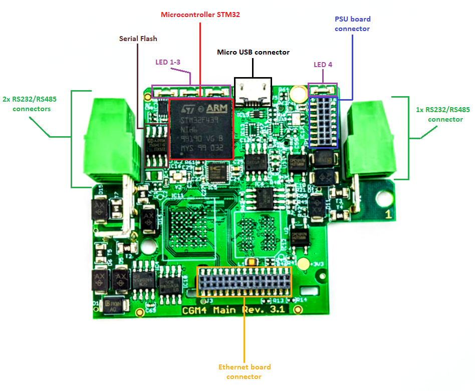
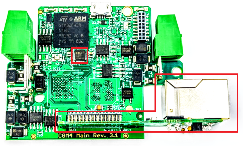
Main Board
Power Supply Board
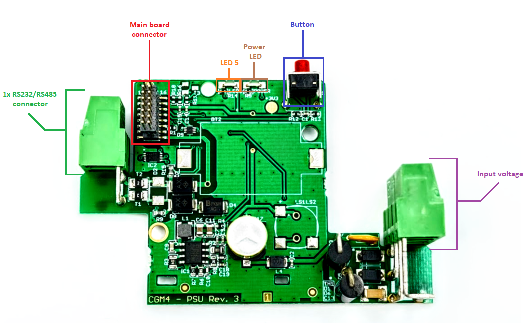
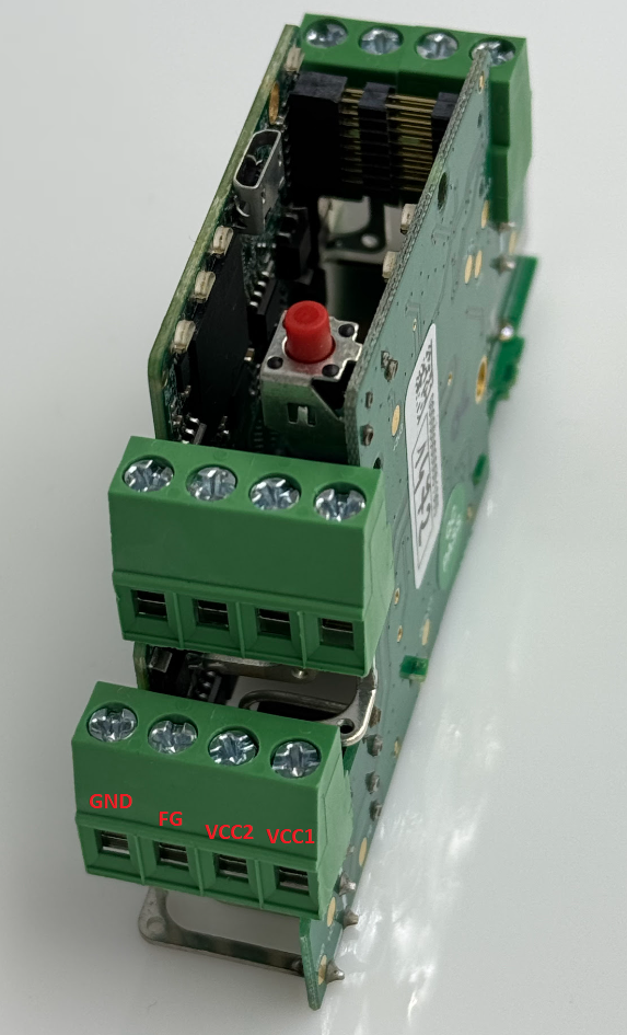
Power input & RS232/RS485 ports
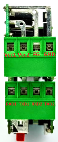
- Vcc1, Vcc2 - power supply input 12-30 VDC
- FG - frame ground
- GND - power supply ground
RS232/RS485 ports depend on the device variant.
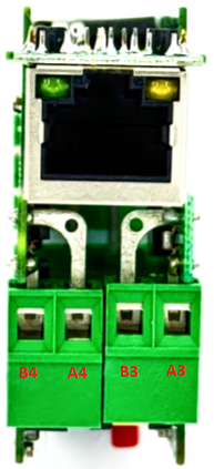
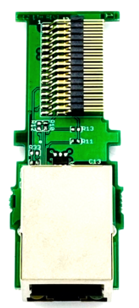
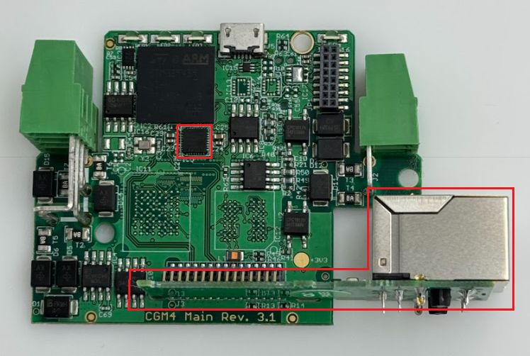
Ethernet
To support the Ethernet network interface communication, the network adapter available in the kit must be installed on the module (pay attention to its correct installation). This interface is supported by the external IP101G physical layer which communicates with the STM32 microcontroller.
Programming
STM32 Open IoT and IIoT Gateways (P10 - P12)
Install IDE & Programmer
Download and install STM32CubeIDE for ability to creating own programs. For device programming, you must install STM32CubeProgrammer. Follow the instructions located on the producer's site. Software is available on Windows, Linux and macOS. Of course, there is a possibility of using other IDEs, but Cube is dedicated to STM32 MCUs and provides a lot of compatible libraries.
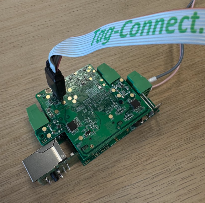
Connect the programmer
STM32 IoT and IIoT Gateways can be programmed only with the MCU producer's external hardware programmer - ST LINK - connected via the Tag-Connect connector to the board. After connecting it to the board and a PC, the device should be available in Device Manager as STM32 STLink in Universal Serial Bus devices.
Connect the power supply
The gateway works with 12-30V DC power supplies. Make sure your supply is properly set.
Create your own programs
After all of the above steps are done, the device should be ready to be programmed. Example scripts and repositories are available here.
Build, flash and monitor the device
There are two options for building your program.
STM32CubeIDE
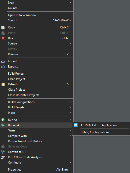
Right click on your project and choose Debug As -> STM32 C/C++ Application. It should generate the .elf file in the Debug folder in the project.
CMake
The project can also be built in STM32CubeIDE via CMake. For more information and instructions check the producer's instructions.
Flash
There are two ways to flash the device.
STM32CubeProgrammer
It is the most recommended to use Programmer.
Open the software and connect it to the ST-Link programmer.
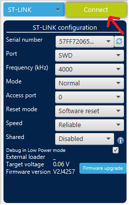
After successful connect you should see the device memory with addresses on the screen.
Click on the down-arrow on the left side of the screen and browse for your file path.
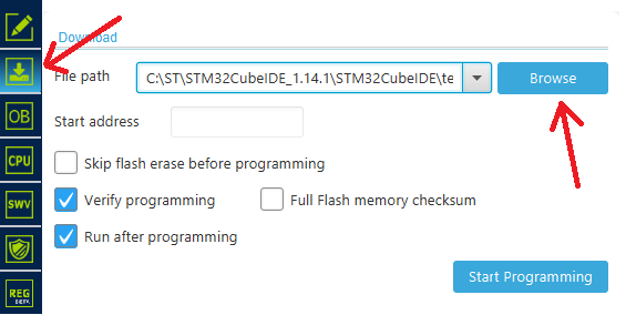
Find the .elf file (it should always be generated in the Debug folder in your project's path).
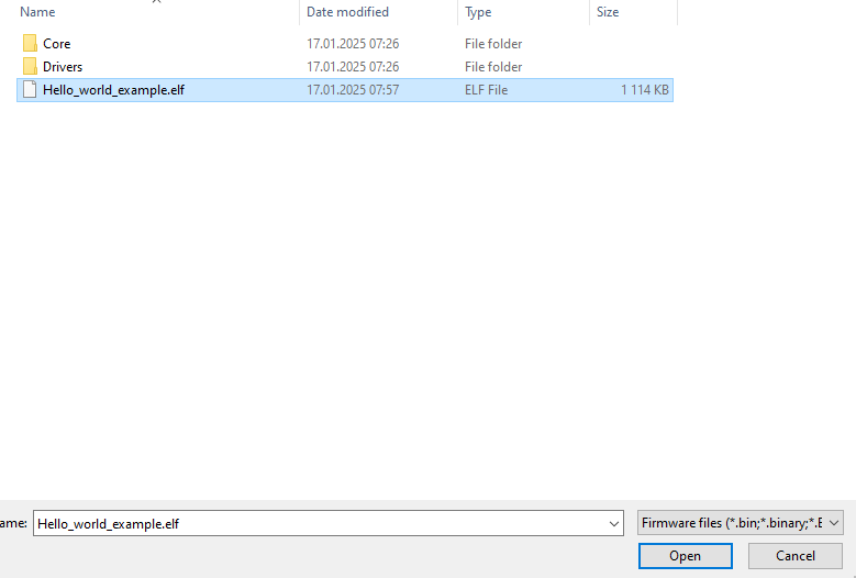
Click "Open".
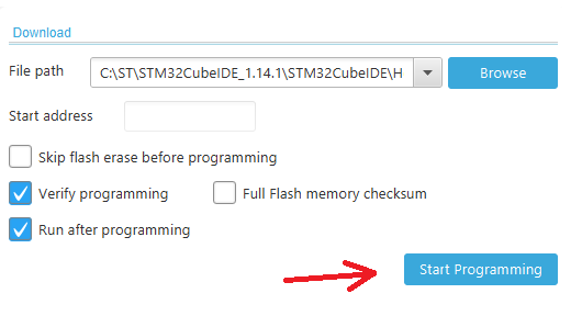
Click "Start Programming".
If programming have been done successfully, you should see on the screen some messages in pop-up windows and Log console.
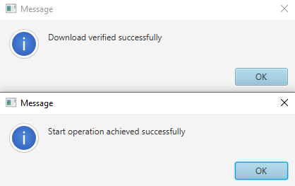
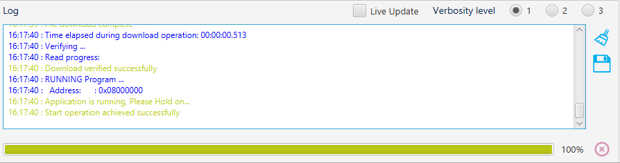
The Gateway has been programmed.
Flashing in IDE
It is possible to flash your program directly from STM32CubeIDE. However, this method works only with some simple, small projects without using CMake. Just click on the  icon in the IDE, and after a few seconds, the device should be programmed. If it doesn't work, use the previous method.
Monitoring
You can connect the device to your computer using a console and Serial connection. To do so, you need two USB cables and a USB -> UART Converter (for example, C37).
If the connection is correct, the device will be visible as a USB Serial Port (COMx/ttyUSB). You can use any console terminal with the Serial option. The baudrate depends on USB UART settings in the project.
Pin Map
STM32 Open IoT and IIoT Gateways (P10 - P12)
CGM Rev. 3.1
| Element | Connection |
| LED | |
| Power LED | +3V3 |
|
LED1 |
PG6 |
| LED2 | PH14 |
| LED3 | PA10 |
| LED4 | PH12 |
| LED5 | PI9 |
| ST3232BTR_1 UART RS232 Transceiver (P10 & P11) | |
| T1_IN | USART1_TXD |
| T2_IN | USART6_TXD |
| T1_OUT | TXD1 |
| T2_OUT | TXD2 |
| R1_IN | RXD1 |
| R2_IN | RXD2 |
| R1_OUT | USART1_RXD |
| R2_OUT | USART6_RXD |
| V+ |
C7 (100nF) |
| V- | C8 (100nF) |
| C1+ | C5 (100nF) |
| C1- | C5 (100nF) |
| C2+ | C6 (100nF) |
| C2- | C6 (100nF) |
| ESDA25-4BP6 ESD protection | |
| I/O_1 | RXD2 |
|
I/O_2 |
TXD1 |
| I/O_3 | RXD1 |
| I/O_4 | TXD2 |
| GND | FGC |
| ST3232BTR_2 UART RS232 Transceiver (P10) | |
| T1_IN | USART3_TXD |
| T2_IN | UART7_TXD |
| T1_OUT | B_4 |
| T2_OUT | B_3 |
| R1_IN | A_4 |
| R2_IN | A_3 |
| R1_OUT | USART3_RXD |
| R2_OUT | UART7_RXD |
| V+ |
C64 (100nF) |
| V- | C65 (100nF) |
| C1+ | C57 (100nF) |
| C1- | C57 (100nF) |
| C2+ | C50 (100nF) |
| C2- | C50 (100nF) |
| ESDA25-4BP6 ESD protection | |
| I/O_1 | - |
|
I/O_2 |
- |
| I/O_3 | B_4 |
| I/O_4 | A_4 |
| GND | FGC |
| MAX481CSA_1 UART RS485 Transceiver (P12) | |
| DI | USART1_TXD |
| DE | RS485_DRIVER_ENABLE1 |
| RE/ | RS485_RECEIVER_ENABLE1 |
| RO | USART1_RXD |
| A | TXD1 |
| B | RXD1 |
| MAX481CSA_2 UART RS485 Transceiver (P12) | |
| DI | USART6_TXD |
| DE | RS485_DRIVER_ENABLE2 |
| RE/ | RS485_RECEIVER_ENABLE2 |
| RO | USART6_RXD |
| A | TXD2 |
| B | RXD2 |
| MAX481CSA_3 UART RS485 Transceiver (P11 & P12) | |
| DI | USART3_TXD |
| DE | RS485_DRIVER_ENABLE3 |
| RE/ | RS485_RECEIVER_ENABLE3 |
| RO | USART3_RXD |
| A | A_3 |
| B | B_3 |
| MAX481CSA_4 UART RS485 Transceiver (P11 & P12) | |
| DI | UART7_TXD |
| DE | RS485_DRIVER_ENABLE4 |
| RE/ | RS485_RECEIVER_ENABLE4 |
| RO | UART7_RXD |
| A | A_4 |
| B | B_4 |
| USBLC6-2P6 ESD protection | |
| VCC | VBUS_ADC, MICROUSB_B_U254-051T-4BH83-F1S (PIN1) |
| GND | GND |
| IO1_A | MICROUSB_B_U254-051T-4BH83-F1S (PIN2) |
| IO2_A | MICROUSB_B_U254-051T-4BH83-F1S (PIN3) |
| IO1_B | BOOTLOADER_TX |
| IO2_B | BOOTLOADER_RX |
| Serial EEPROM M24C08-RMC6TG | |
| E0 |
GND |
| E1 |
GND |
| E2 |
+3V3 |
| VSS |
GND |
| VCC |
+3V3 |
| WC/ |
GND |
| SCL |
I2C1_SCL |
| SDA |
I2C1_SDA |
| Serial Flash A25LQ64M | |
| CS# | SPI2_SS |
| SO | SPI2_MISO |
| WP# | SPI2_W |
| VSS | GND |
| VCC | +3V3 |
| HOLD# | SPI2_IO3 |
| SCLK | SPI2_SCK |
| SI | SPI2_MOSI |
| IP101GRI ETHERNET PHY transceivers | |
| MDC |
ETH_MDC |
| MDIO |
ETH_MDIO |
| MDI_TP |
TXD+ |
| MDI_TN |
TXD- |
| MDI_RP |
RXD+ |
| MDI_RN |
RXD- |
| X2 | - |
| X1 | ETH_MCO |
| RESET_N | ETH_RESET_N |
| ISET | ETH_ISET |
| LED0/PHY_AD0 | ETH_LED0/PHY_AD0 |
| LED3/PHY_AD3 | ETH_LED3/PHY_AD3 |
| TEST_ON | - |
| REGOUT | C23 (100 nF), C29 (10 uF) |
| VDDIO | +3V3 |
| AVDD33 | +3V3 |
| GND | GND |
| TXEN | ETH_TX_EN |
| TXER/FXSD | - |
| TXCLK/50M_CLKI | ETH_RMII_REF_CLK |
| TXD0 | ETH_TXD0 |
| TXD1 | ETH_TXD1 |
| TXD2 | - |
| TXD3 | - |
| RXDV/CRS_DV/FX_HEN | ETH_RXDV/CRS_DV |
| RXCLK/50M_CLKO | - |
| RXD0 | ETH_RXD0 |
| RXD1 | ETH_RXD1 |
| RXD2 | - |
| RXD3 | - |
| RXER/INTR_32 | - |
| COL/RMII | ETH_COL/RMII |
| CRS/LEDMOD | - |
| STM32 F439NIH6 | |
| PA0 | - |
| PA1 | ETH_RMII_REF_CLK |
| PA2 | ETH_MDIO |
| PA3 | - |
| PA4 | - |
| PA5 | - |
| PA6 | SWITCH |
| PA7 | ETH_RXDV/CRS_DV |
| PA8 |
ETH_MCO |
| PA9 | BUZZER_PWM |
| PA10 | LED_A3 |
| PA11 | USB_DM BOOTLOADER_RX |
| PA12 | USB_DP BOOTLOADER_TX |
| PA13 | JTMS |
| PA14 | JTCK |
| PA15 | CONF2 |
| PB0 | ETH_LED0/PHY_AD0 |
| PB1 | ETH_LED3/PHY_AD3 |
| PB2 | BOOT1 |
| PB3 | SW0 |
| PB4 | USART1_RXD |
| PB5 | USART1_TXD |
| PB6 | USART1_TXD |
| PB7 | USART1_RXD |
| PB8 | I2C1_SCL |
| PB9 | I2C1_SDA |
| PB10 | USART3_TXD |
| PB11 | USART3_RXD |
| PB12 | USART3_RXD |
| PB13 | USART3_TXD |
| PB14 | - |
| PB15 | - |
| PC0 | SD_NWE |
| PC1 | ETH_MDC |
| PC2 | - |
| PC3 | - |
| PC4 |
ETH_RXD0 |
| PC5 | ETH_RXD1 |
| PC6 | USART6_TXD |
| PC7 | USART6_TXD |
| PC8 | CONF4 |
| PC9 | CONF1 |
| PC10 | BOOTLOADER_TX |
| PC11 | BOOTLOADER_RX |
| PC12 | CONF3 |
| PC13 | RTC_AF1 |
| PC14 | OSC32_IN |
| PC15 | OSC32_OUT |
| PD0 | D2 |
| PD1 | D3 |
| PD2 | CONF6 |
| PD3 | - |
| PD4 | NOR_NOE |
| PD5 | NOR_NWE |
| PD6 | NOR_NWAIT |
| PD7 | NOR_NE1 |
| PD8 | D13 |
| PD9 | D14 |
| PD10 | D15 |
| PD11 | A16 |
| PD12 | A17 |
| PD13 | A18 |
| PD14 | D0 |
| PD15 | D1 |
| PE0 | SD_LDOM |
| PE1 | SD_UDOM |
| PE2 | - |
| PE3 | A19 |
| PE4 | A20 |
| PE5 | A21 |
| PE6 | - |
| PE7 | D4 |
| PE8 | D5 |
| PE9 | D6 |
| PE10 | D7 |
| PE11 | D8 |
| PE12 | D9 |
| PE13 | D10 |
| PE14 | D11 |
| PE15 | D12 |
| PF0 | A0 |
| PF1 | A1 |
| PF2 | A2 |
| PF3 | A3 |
| PF4 | A4 |
| PF5 | A5 |
| PF6 | UART7_RXD |
| PF7 | UART7_TXD |
| PF8 | VBUS_ADC |
| PF9 | L2 |
| PF10 | L1 |
| PF11 | SD_NDRAS |
| PF12 | A6 |
| PF13 | A7 |
| PF14 | A8 |
| PF15 | A9 |
| PG0 | A10 |
| PG1 | A11 |
| PG2 | A12 |
| PG3 | A13 |
| PG4 | A14 |
| PG5 | A15 |
| PG6 | LED_A1 |
| PG7 | DIP_SWITCH |
| PG8 | SD_CLK |
| PG9 | USART6_RXD |
| PG10 | USART6_RXD |
| PG11 | ETH_TXEN |
| PG12 | - |
| PG13 | ETH_TXD0 |
| PG14 | ETH_TXD1 |
| PG15 | SD_NCAS |
| PH0 | OSC+IN |
| PH1 | OSC_OUT |
| PH2 | SD_CKE0 |
| PH3 | SD_NE0 |
| PH4 | I2C2_SCL |
| PH5 | I2C2_SDA |
| PH6 | - |
| PH7 | - |
| PH8 | RS485_DRIVER_ENABLE1 |
| PH9 | RS485_RECEIVER_ENABLE1 |
| PH10 | RS485_DRIVER_ENABLE2 |
| PH11 |
RS485_RECEIVER_ENABLE2 |
| PH12 | LED_A4 |
| PH13 | - |
| PH14 | LED_A2 |
| PH15 | CONF5 |
| PI0 | WP#//ACC |
| PI1 | SPI2_SCK |
| PI2 | SPI2_MISO |
| PI3 | SPI2_MOSI |
| PI4 | SPI2_W |
| PI5 | SPI2_IO3 |
| PI6 | ETH_RST |
| PI7 | RS485_DRIVER_ENABLE3 |
| PI8 | RS485_RECEIVER_ENABLE3 |
| PI9 | LED_5 |
| PI10 | RS485_TERMINATION_ENABLE4 |
| PI11 | RS485_TERMINATION_ENABLE3 |
| PI12 | SPI2_SS |
| PI13 | - |
| PI14 | RS485_RECEIVER_ENABLE4 |
| PI15 | RS485_DRIVER_ENABLE4 |
Optional
| Element | Connection |
| HTS221 | |
| VDD | +3V3 |
| CS | +3V3 |
| GND | GND |
| SCL/SPC | I2C2_SCL |
| SDA/SDI/SDO | I2C2_SDA |
| DRDY | - |
| LIS3DH | |
| VDD_IO | +3V3 |
| NC | - |
| NC | - |
|
SCL/SPC |
I2C2_SCL |
|
GND |
GND |
| SDA/SDI/SDO | I2C2_SDA |
| SDO/SAO | - |
| CS | +3V3 |
| ADC1 | - |
| ADC2 | - |
| VDD | +3V3 |
| ADC3 | - |
| GND | GND |
| INT1 | - |
| RES | GND |
| INT2 | - |
| LSM6DS33 | |
| GND, GND, RES, RES, RES, RES | GND |
| INT1 | - |
| INT2 | - |
| VDDIO | +3V3 |
| SCL | I2C2_SCL |
| SDA | I2C2_SDA |
| SDO | - |
| CS | +3V3 |
| NC | - |
| RES | GND |
| VDD | +3V3 |
| SI7006-A20/SI7020-A20 | |
| SDA | I2C2_SDA |
| SCL | I2C2_SCL |
| GND | GND |
| VDD | +3V3 |
| DNC1 | - |
| DNC2 | - |
Peripherals
RGB LED
STM32 Open IoT and IIoT Gateways (P10 - P12)
The Gateway is equipped with 5 RGB user LEDs. 4 are mounted directly to the board, and the fifth is next to the not-programmable blue power LED on the PSU board.

Switch
STM32 Open IoT and IIoT Gateways (P10 - P12)
The Open IoT Gateway contains a tactile switch mounted to the PSU board, which can be programmed directly in the MCU.

RS232 and RS485
STM32 Open IoT and IIoT Gateways (P10 - P12)
The Gateway has 4 RS232/RS485 sockets depending on the version.
P10 (4x RS232)
The P10 gateway is equipped with 2x ST3232BTR to ensure transmission in RS232 standard.

P11 (4x RS485)
The P11 gateway is equipped with 2x MAX481CSA to ensure transmission in RS485 standard.

P12 (2x RS232, 2x RS485)
The P12 gateway is equipped with 1x ST3232BTR and 2x MAX481CSA to ensure transmission both in RS232 and RS485 standardsm

Ethernet PHY
STM32 Open IoT and IIoT Gateways (P10 - P12)
The Ethernet interface is provided by the IP101G physical layer. An external board with an RJ45 socket ensures a wired connection to the network.

MicroUSB
STM32 Open IoT and IIoT Gateways (P10 - P12)
MicroUSB ensures access straight to UART interface (UART4). The Open IoT Gateway does not have inbuild FTDI converter so an external USB to UART FTDI converter is needed to run a serial port monitor on a PC.

I2C EEPROM
STM32 Open IoT and IIoT Gateways (P10 - P12)
The Open IoT Gateway has a built-in Serial EEPROM with a secure element connected to the STM32 via I2C bus.

Serial Flash
STM32 Open IoT and IIoT Gateways (P10 - P12)
The Gateway has a Serial flash memory which can be programmed via SPI.

I2C Sensors (optional)
STM32 Open IoT and IIoT Gateways (P10 - P12)
There is a possibility of connecting peripheral I2C sensors. The board has dedicated pins for soldering devices. Below is a proposal for additional sensors that match the hardware.

- LSM6DS33 - 3D accelerometer and 3D gyroscope
- LIS3DH - 3-axis "nano" accelerometer
- HTS221 - capacitive digital sensor for relative humidity and temperature measurements
- SI7006-A20 / SI7020-A20 - humidity and temperature sensor
The presented devices are not included in the Open IoT Gateway.
Examples
Hello World
STM32 Open IoT and IIoT Gateways (P10 - P12)
Link to repositories:
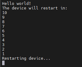
This example uses UART4 in the MCU which is reserved for the USB UART communication. A simple string is printed on the console and then the device restarts after 10 seconds of countdown. Use 115200 baudrate.
LED
STM32 Open IoT and IIoT Gateways (P10 - P12)
Link to repositories:
A simple blinking LED example intended for the Open IoT Gateway. Lighting LED will be changed every 1 second from LED1 to LED5.
Switch
STM32 Open IoT and IIoT Gateways (P10 - P12)
Link to repositories:
Simple tactile switch example intended for the Open IoT Gateway. After flash, connect device to a PC and open port in Console Terminal. The information about the switch pressed state will be displayed in the console as shown below.

RS232/RS485
STM32 Open IoT and IIoT Gateways (P10 - P12)
Link to repositories:
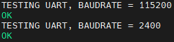
This script tests internal communication between serial ports with the possible lowest (2400) and highest (115200) baudrate.
For this example, connect each port's transceiver with the receiver:
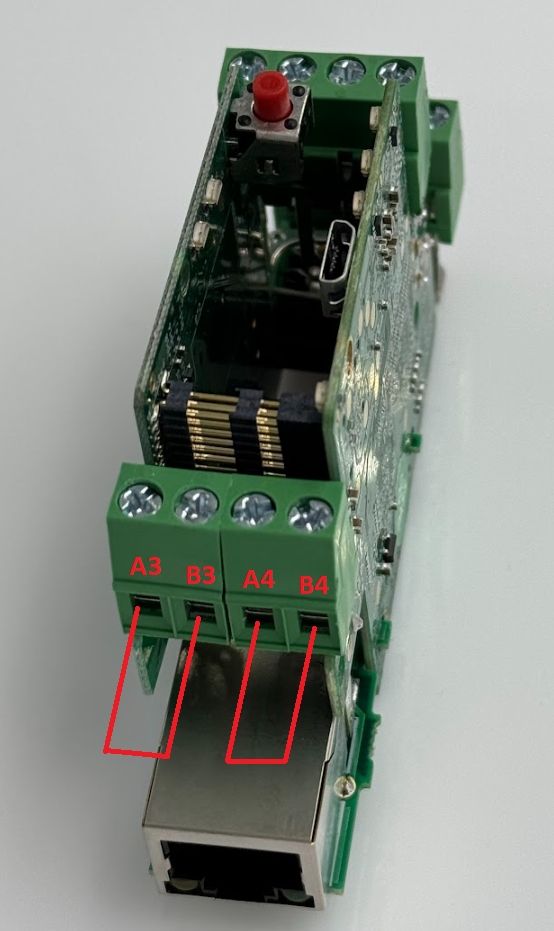
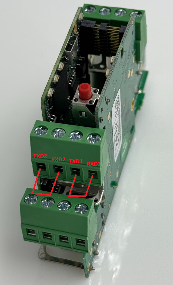
Default settings:
- baud rate: 115200
- data bits: 8
- parity bits: 0
- stop bits: 1
- receiver timeout: 3s
If the connection is right, you should see the messages shown below for each U(S)ART:
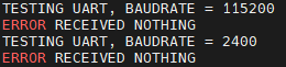
If something goes wrong with the connection, you will see the message for a specific port like below:
Ethernet
STM32 Open IoT and IIoT Gateways (P10 - P12)
Link to repositories:
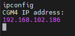
This example allows you to check the Gateway's IP address. Connect the device via USB/UART converter and choose correct COM/ttyUSB port. Remember to connect the IoT Gateway to the network using an Ethernet cable. Type in terminal "ipconfig". If your network connection works properly, IP address will be displayed as below:
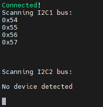
I2C scanner
STM32 Open IoT and IIoT Gateways (P10 - P12)
Link to repositories:
A simple program for scanning and displaying addresses of connected devices via I2C bus.
Contact Us
- Main web page
- E-mail:
online@redisage.com - Phone number:
+48 71 70 00 140 - Address:
NSG 4L Sp. z o.o.
ul. Trzy Lipy 3B
80-172 Gdańsk
(POLSKA) - More information
Common Resources
Source of common resources used across the Open IoT and IIoT Gateways documentation
Tables
Specifications
|
Redisage PN |
P10 |
P11 |
P12 |
||||
|
Ports |
RS232 |
4x |
- |
2x |
|||
|
RS485 |
- |
4x |
2x |
||||
|
RS232/RS485 |
- |
- |
- |
||||
|
Microcontroller |
STM32 |
||||||
|
WiFi |
N/A | ||||||
|
Bluetooth |
N/A | ||||||
|
SMA socket connector for WiFi/BT antenna |
|||||||
|
Tactile switch |
|||||||
|
Power |
Voltage |
12-30 VDC |
|||||
|
Power |
< 1 W |
||||||
|
Frame ground protection |
yes |
||||||
|
Baud rate |
up to 115200 bps |
||||||
|
LED indicators |
power, link activity, programmable RGB |
||||||
|
RS485 termination |
120 ohm manually enabled |
||||||
|
Connector |
RS232/RS485 |
8-pin terminal block max. 2.5 mm2 wire |
|||||
|
Power |
3-pin terminal block max. 2.5 mm2 wire |
||||||
|
Ethernet |
RJ45 |
||||||
|
Transmission |
RS485 |
max. 1,200 m at 9.6 kbps; max. 400 m at 115.2 kbps |
|||||
|
RS232 |
max. 15 m at 115.2 kbps |
||||||
|
Mounting and enclosure |
DIN rail, plastic PA - UL 94 V0, black/green |
||||||
|
Temperatures |
-40°C to +75°C operating and storage |
||||||
|
Humidity |
10 - 90% RH, non-condensing |
||||||
|
ESD protection |
±4 kV contact discharge / ±8 kV air discharge |
||||||
|
Certification |
CE, RoHS, EMC, LVD |
||||||
|
Norms |
61000-6-2 - Immunity standard for industrial environments 61000-6-4 - Emission standard for industrial environments |
||||||
Pin assignments
|
P10
|
P11
|
|
P12
|
|
Introduction
STM32 Open IoT and IIoT Gateways (P10 - P12)
Open IoT Gateway is also called as a PAC (Programmable Automation Controller). PAC products combine the functionality and openness of PC, the reliability of a programmable logic unit like PLC and the intelligence of I/O modules with flexible software tools for a wide range of applications from data acquisition, process control, motion control to energy and building management.
Our PAC family includes FreeRTOS PACs for different requirements in OS, CPU and development platforms.
The P10 - P12 gateways are based on STM32 ARM Cortex-M4.