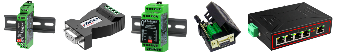
| **C20 C21 C22 C23 C24 C25** **[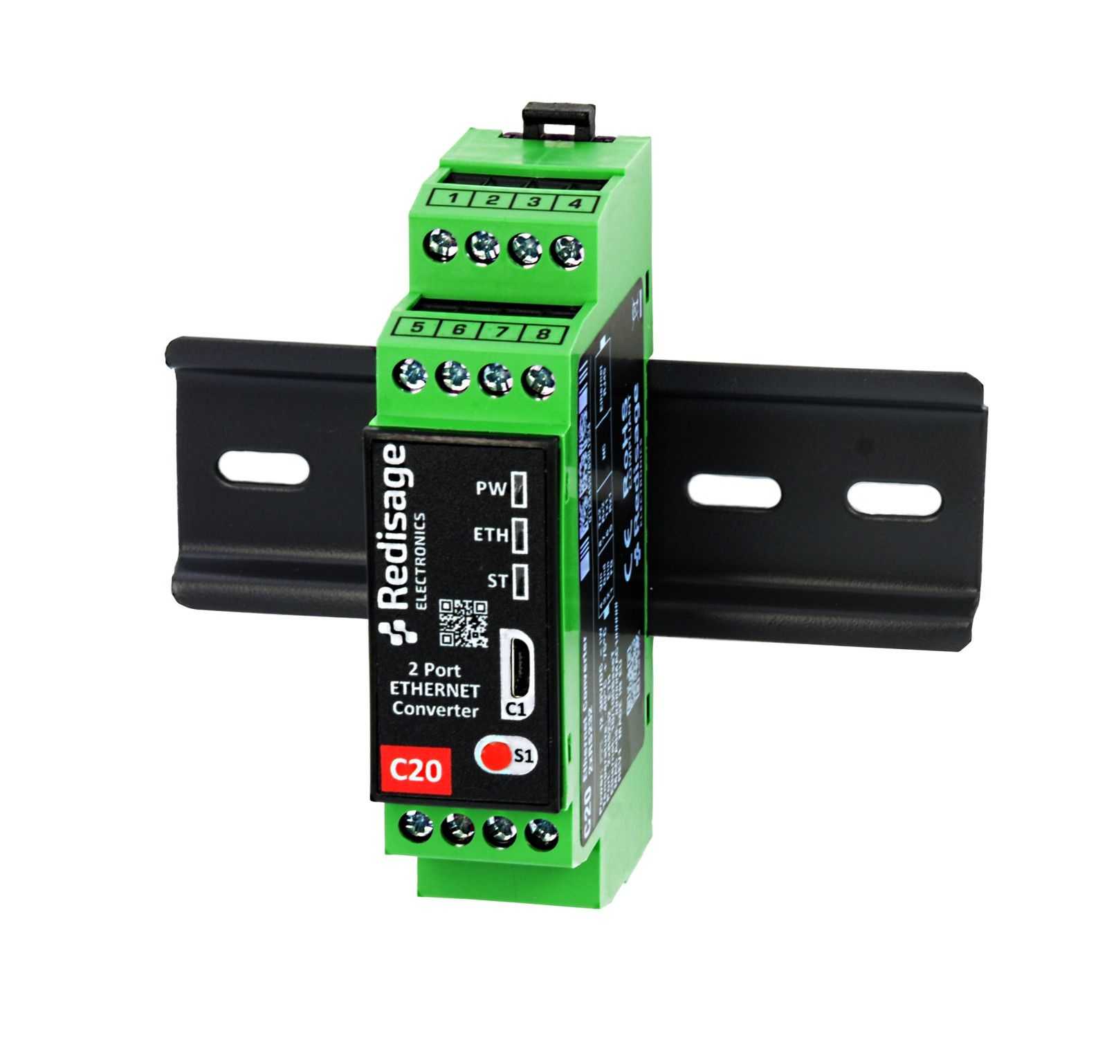](https://doc.redisage.com/uploads/images/gallery/2024-03/8687e11c-6546-4888-bb0e-5ec48c9a7daf.jpg)** | **Features** - Ethernet converter to RS232/RS485 - ESD protection for the RS485 data line - Power supply: +12 to +30 VDC - Transmission speed up to 115200 bps - Tx, Rx and power LED indicators - RS485 embedded termination 120 ohm - Operating temperatures: -40°C to +75°C - DIN rail mounting - Dimensions: 90x56.4x22.5 mm - 3 years warranty - Customization of OEM is welcomed |
| **Redisage PN** | **C20** | **C21** | **C22** | **C23** | **C24** | **C25** | |
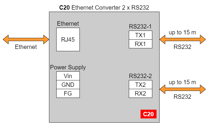
| Ports | RS232 | 2x | - | - | 4x | - | 2x |
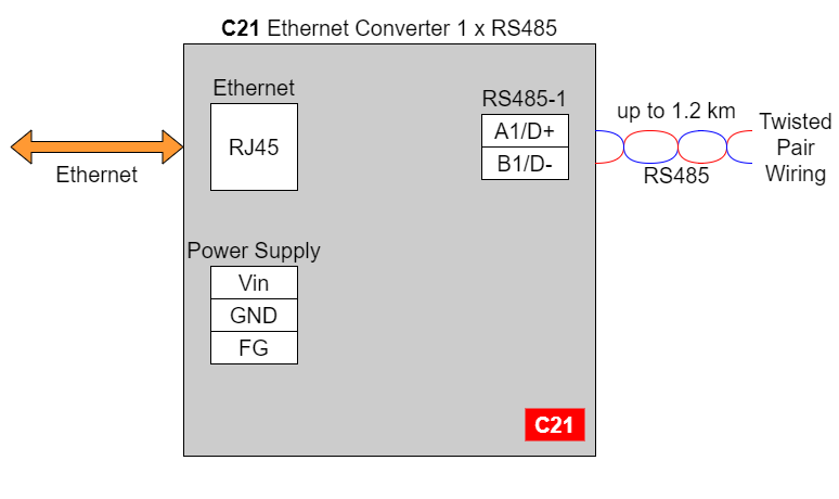
| RS485 | - | 1x | - | - | 4x | 2x | |
| RS232/RS485 | - | - | 2x | - | - | - | |
| Microcontroller | ESP32 | STM32F4 | |||||
| WiFi | N/A | ||||||
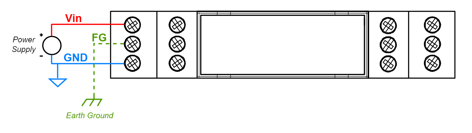
| Power | Voltage | 12-30 VDC | |||||
| Power | < 1 W | ||||||
| Frame ground connection | yes | ||||||
| Baud rate | up to 115200 bps | ||||||
| LED indicators | communication Tx, Rx and power | ||||||
| RS485 termination | 120 ohm manually enabled | ||||||
| Connector | RS232/RS485 | 8-pin terminal block max. 2.5 mm2 wire | |||||
| Power | 3-pin terminal block max. 2.5 mm2 wire | ||||||
| Ethernet | RJ45 | ||||||
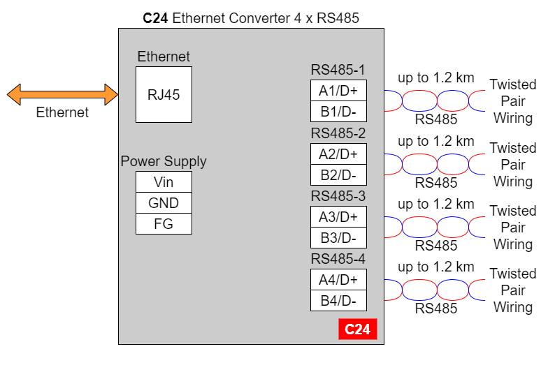
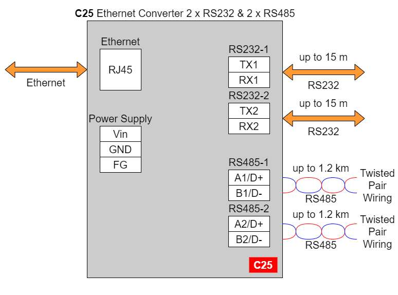
| Transmission distance | RS485 | max. 1,200 m at 9.6 kbps; max. 400 m at 115.2 kbps (Belden 9841 2P twisted-pair cable, if different cables are used, the transmission distance may change) | |||||
| RS232 | max. 15 m at 115.2 kbps | ||||||
| Mounting and enclosure | DIN rail, plastic PA - UL 94 V0, black/green | ||||||
| Temperatures | -40°C to +75°C operating and storage | ||||||
| Humidity | 10 - 90% RH, non-condensing | ||||||
| ESD protection | ±4 kV contact discharge / ±8 kV air discharge | ||||||
| Certification | CE, RoHS, EMC, LVD | ||||||
| Norms | 61000-6-2 - Immunity standard for industrial environments 61000-6-4 - Emission standard for industrial environments | ||||||
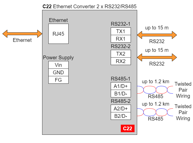
In the C22 converter user should use only RS232 or only RS485 interface of one port as they occupy the same internal bus of the device.
#### C23 - Ethernet Converter 4 x RS232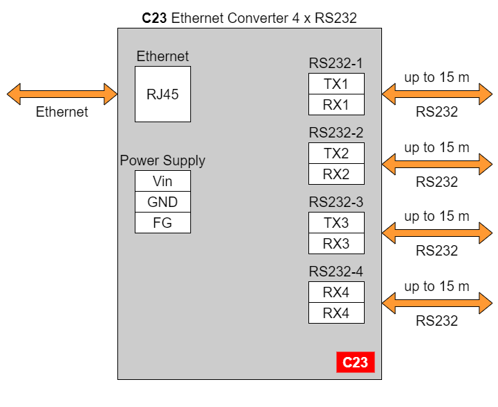
| **C20** [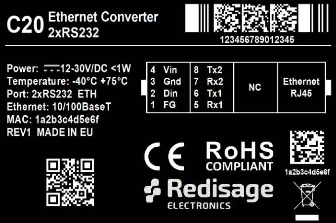](https://doc.redisage.com/uploads/images/gallery/2024-03/cb11de82-9b9c-441b-a5ec-a154b2974af1.png) | **C21** **[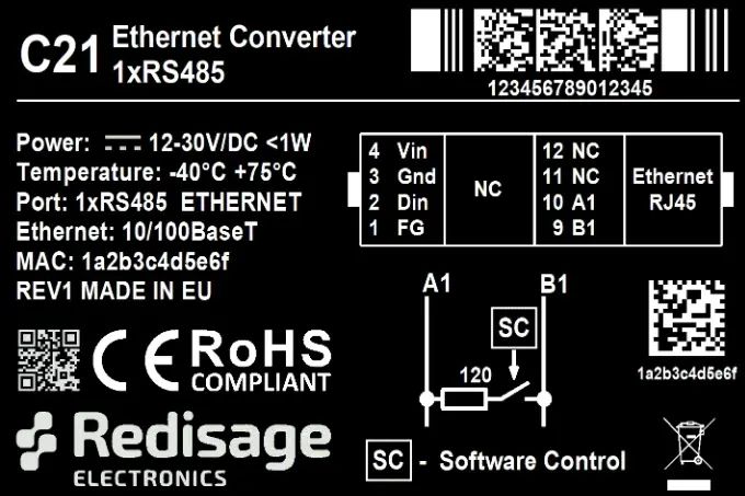](https://doc.redisage.com/uploads/images/gallery/2024-03/9ec3cdd8-81fa-43f3-b5d6-321d3e380273.jpg)** |
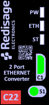
| **C22** **[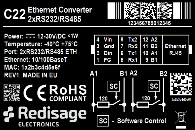](https://doc.redisage.com/uploads/images/gallery/2024-03/b256a7e1-4bcb-44a8-8d61-d9973cc82d4e.png)** | **C23** **[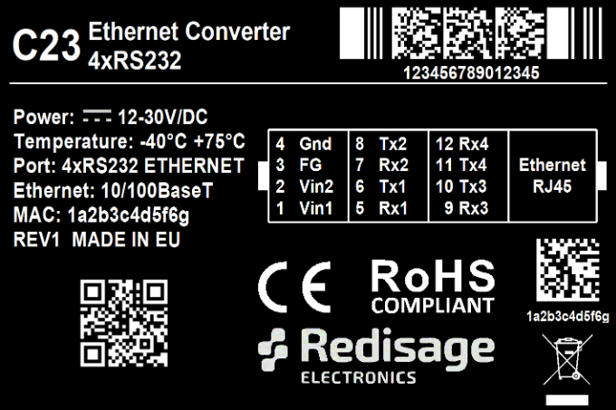](https://doc.redisage.com/uploads/images/gallery/2024-03/c0d89b16-0d72-4553-aacd-745659a94c87.png)** |
| **C24** **[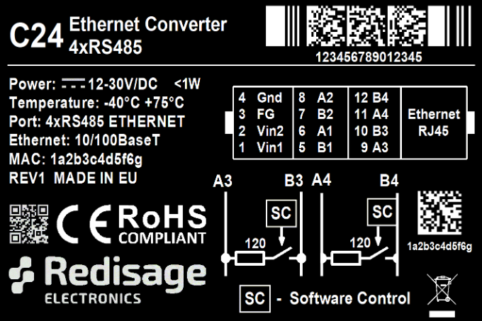](https://doc.redisage.com/uploads/images/gallery/2024-03/939889bb-f557-4d08-b093-d2ac790a3bce.png)** | **C25** [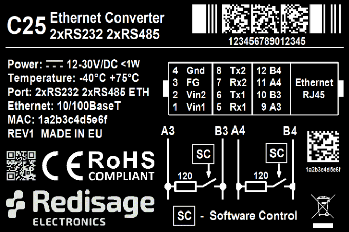](https://doc.redisage.com/uploads/images/gallery/2024-03/46bb1368-b158-4f8d-8114-304a359a9685.png) |
| **Item** | **Description** | |
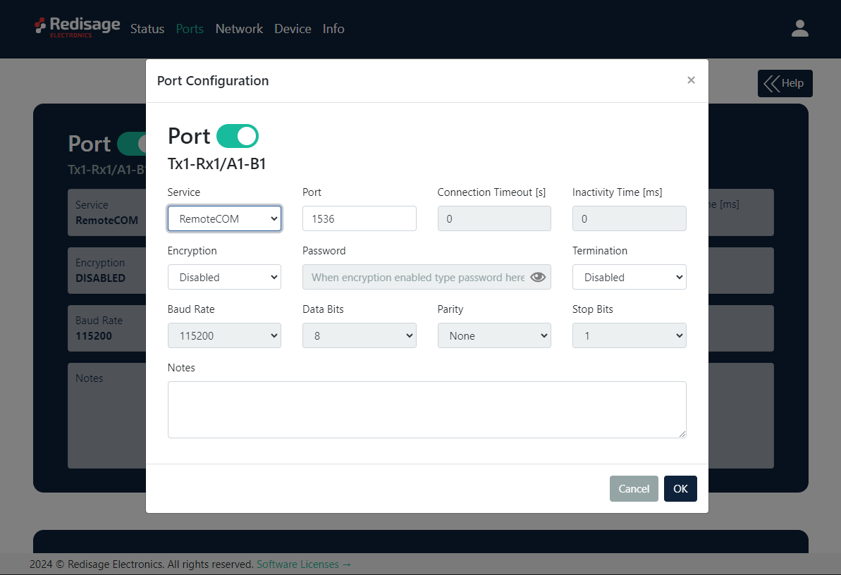
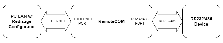
| Service | RemoteCOM | The RemoteCOM option lets to attach the port to a computer running the [Redisage Configurator](https://doc.redisage.com/books/remotecom/page/redisage-configurator "Redisage Configurator") as if it would be physically present in the computer. |
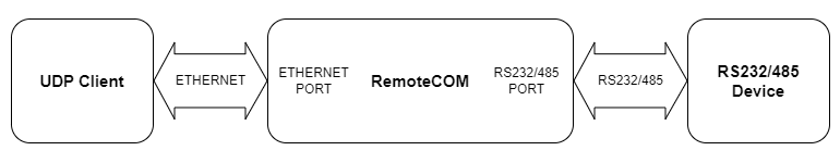
| TCP Socket | TCP/UDP Socket exposes this port as a regular network socket - connect to this socket with own software and write/read data to send/receive data over the serial port without any additional software or serial port handling. | |
| UDP Socket | ||
| Port | The service number - the device has an “IP Address” by which it is identified and a couple of services running on it. It's required to tell the device which service should be in use by entering this device's IP address and the port number in the RemoteCOM client or user’s software. | |
| Connection Timeout \[s\] | The time specifying how often (every how many seconds) the "keep alive" packet will be sent to check if the client is still connected. Value 0 means that the connection is kept permanently without any timeout. | |
| Inactivity Time \[ms\] | The maximum allowed time in milliseconds during which there is no data transfer. When connection is inactive for the time longer or equal to the entered value, then it will be closed. Value 0 means there is no measure of the inactivity time at all. | |
| Encryption | Determine how the data is protected 'in flight' over a network. It is available only with the RemoteCOM service. Once enabled, it is necessary to set the password. | |
| Password | Protect the communication between the device and various clients - keep it secret! Same settings have to appear in clients - without the correct passwords, a client will not be able to connect at all. | |
| Termination | Enable/disable termination on the RS line. | |
| Baud Rate | Determine the port's transmission speed over the data channel. | |
| Data Bits | Determine the number of data bits in the port's message frame. | |
| Parity | Enable/disable parity check in the port's message frame. | |
| Stop Bits | Determine the number of stop bits in the port's message frame. | |
| Notes | These notes are for information only - feel free to write down anything related to this port (device it connects to, etc.). They're also shown in the Configurator during the device discovery - in the other words, they're public. | |
Changing port’s service closes all sockets connected to the ports.
In the UDP mode, port number 15051 is reserved for UDP broadcast service.
Network settings can be changed on the “Network” page. [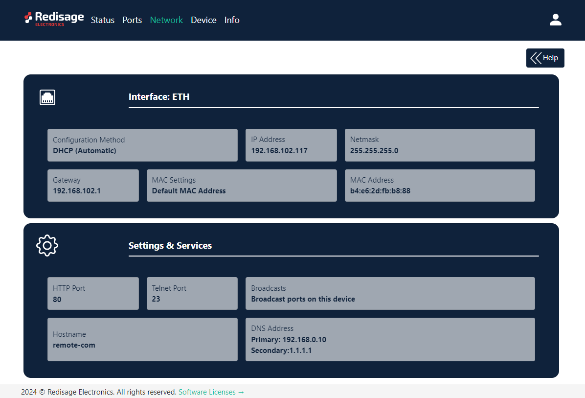](https://doc.redisage.com/uploads/images/gallery/2024-03/8386aa9b-6add-432d-945d-303e590ed269.png) [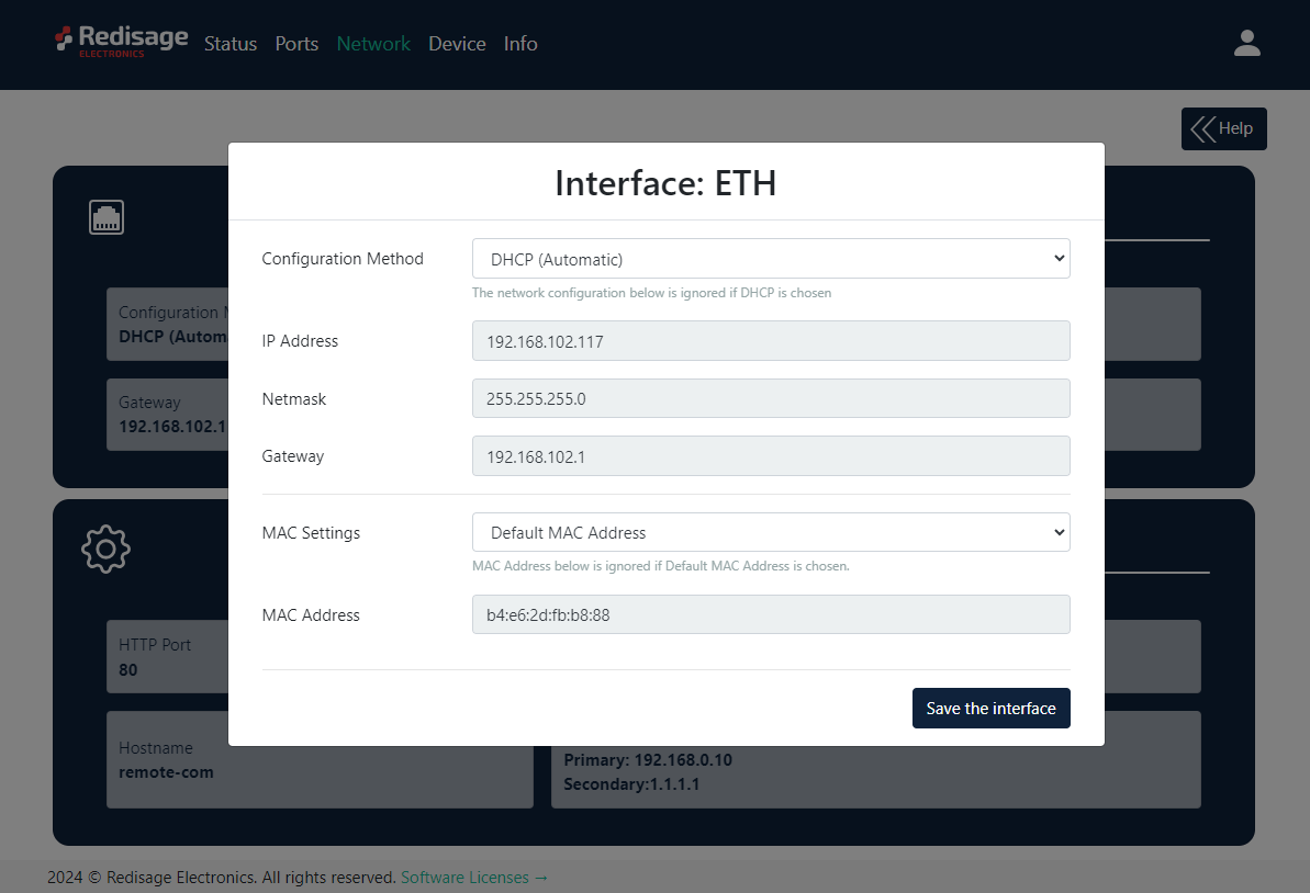](https://doc.redisage.com/uploads/images/gallery/2024-03/98a9fcdf-9549-4d9a-9e04-ef90021cfaff.png)| **Item** | **Description** |
| Configuration Method | Enable/disable the DHCP server. If the DHCP server is disabled, the IP address of the device has to be set manually. |
| IP Address | IP address of the device. |
| Netmask | Netmask associated with the IP address. |
| Gateway | Gateway address currently used by the device. |
| MAC Settings | Allow setting the default MAC address or typing it manually. |
| MAC Address | Allow changing the physical address of the device. |
| **Item** | **Description** |
| HTTP Port | Determine the port of the control panel. |
| Telnet Port | Allow connection with the device via Telnet. |
| Broadcasts | Notify RemoteCOM clients in the same network about this device's existence. With this enabled, the Configurator will automatically set most of the settings correctly after picking the correct port. |
| Hostname | Label that is assigned to the device. |
| DNS Address 1 (Primary) | Primary Domain Name System used by the device. |
| DNS Address 2 | Domain Name System used by the device. |
| **Command** | **Description** |
| help | Print the help. |
| conn | Print active TCP connections. |
| eth\_mac | Print or change MAC address. |
| exit | Close current CLI session. |
| http\_port | Print or change default http port. |
| ipconfig | Print or change the network configuration. |
| net\_stat | Print lwIP statistics. |
| ping | Check internet connection with the desired host. |
| restart | Restart the system. |
| reboot | Same as restart. |
| sys\_heap\_usage | Print current heap usage. |
| telnet\_port | Print or change default telnet port. |
| uart | Print or change uart configuration. |
| uart\_service | Print or change uart\_service configuration. |
| user | Print or change user configuration. |
If any change is made to the port configuration, make sure to apply it with the “Save Changes” button.
#### Reset to factory defaults Reset to factory defaults is possible on the web page in the device section or using the service mode. #### Service mode ##### Procedure to enter service mode for C20 - C22 converters - Turn off the power of the device. - Connect Ethernet converter to the dedicated USB/UART converter via the microUSB port. - Connect the USB/UART converter to the PC. - Open the serial console (default baud rate is 115200 bps). - Press and hold the S1 button. - Turn on the power. - Wait until the ST indicator (red LED) lights up. - Release the S1 button. - If the process is successful, service commands can be typed into the terminal. ##### Procedure to enter service mode for C23 - C25 converters - Install STM32 Virtual COM Port Driver (if it was not done before). - Turn off the power of the device. - Connect Ethernet converter directly to the PC (the dedicated USB/UART converter is not obligatory). - Open the serial console (default baud rate is 115200 bps). - Press and hold the S1 button. - Turn on the power. - Wait until the ST indicator (red LED) lights up. - Release the S1 button. - If the process is successful, service commands can be typed into the terminal. ##### List of commands in the service mode| **Command** | **Description** |
| help | Print the help. |
| credits | Print current credits value for this device. |
| dev\_ident | Print the device identification value. |
| restart | Restart the system. |
| serial\_num | Print the serial number of this device. |
| version | Display the bootloader version. |
| xmodem | Download image to the internal flash using xmodem. |
| defaults | Reset application variables to defaults. |
| ipconfig | Print or change the network configuration. |
| flash\_read | Read bytes from flash memory. |
| md | Read bytes from memory address. |
In the service mode, the “ipconfig” command can only show a last static IP address.
### Additional notes| **Related information and links** | ||
| [Ordering information](https://redisage.com/en/delivery.html) | [Accessories](https://redisage.com/eng_m_Accessory-174.html) | [Similar products](https://redisage.com/search.php?text=+&sort=name&order=a) |
| **Features** | [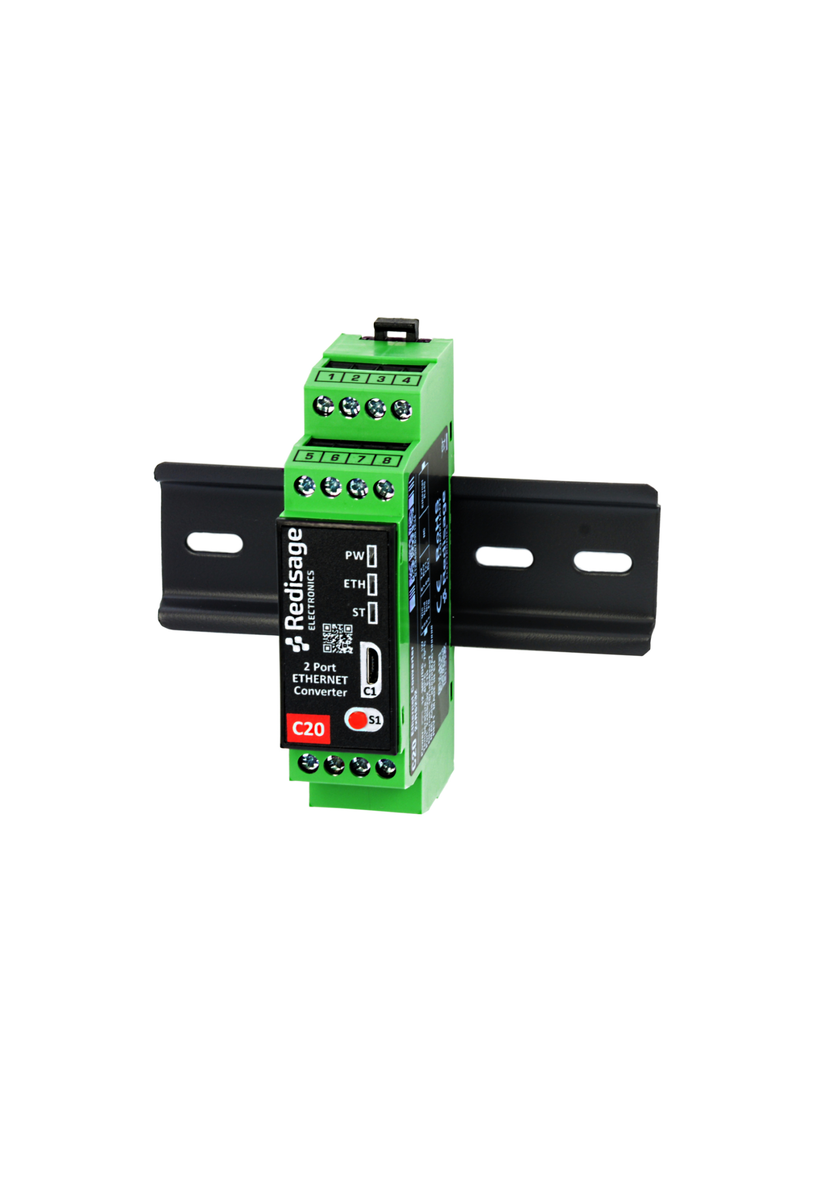](https://doc.redisage.com/uploads/images/gallery/2024-03/c5368820-11b3-4934-ae6d-774d7208eae7.png) |
|---|---|
| Ethernet converter to RS232/RS485 | |
| ESD protection for the RS485 data line | |
| Power supply: +12 to +30 VDC | |
| Transmission speed up to 115200 bps | |
| Tx, Rx and power LED indicators | |
| RS485 embedded termination 120 ohm | |
| Operating temperatures: -40°C to +75°C | |
| DIN rail mounting | |
| Dimensions: 90x56.4x22.5 mm | |
| **3 years warranty** | |
| **Customization of OEM is welcomed** |
| **Converters C20 - C22** | **Converters C23 - C25** | ||||
| [](https://doc.redisage.com/uploads/images/gallery/2024-03/20708068-859a-46bf-8b76-783b7400789a.png) | [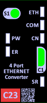](https://doc.redisage.com/uploads/images/gallery/2024-03/66a7b90e-9af7-4b47-ae63-40409f98a845.png) | ||||
| **LED indicator** | **Color** | **Function** | **LED indicator** | **Color** | **Function** |
| PW | Blue | Power | PW | Blue | Power |
| ETH | Green | Network activity | ETH | Green | Network activity |
| ST | Orange | Console mode | CN | Yellow | Console mode |
| Red | Service mode | COM | Green | RS232/RS485 activity | |
| SR | Red | Service mode | |||
| ER | Yellow | Error | |||
In the C22 converter user should use only RS232 or only RS485 interface of one port as they occupy the same internal bus of the device.
# Configuration by the Web Page ## {{@174#bkmrk-remotecom-%28c20---c25}} This page presents capabilities of the Ethernet Converters configuration. First of all, make sure that converter is connected to power supply and to the LAN using a patch cord. If the device has no static IP set up, it will be necessary to obtain its IP address in the local network. User interface is mostly similar for all converters but some subpages might be different for several models depending on amount of interfaces. In order to avoid issues, click on a “Help” button in the top right corner on every page. ### Login To access the web page open the browser, type device’s IP address of the converter (default is **192.168.100.100**). Then log in using user’s personal credentials. If it is a first configuration or the converter had a factory reset, use default login details (login: **admin**, password: **admin123**). [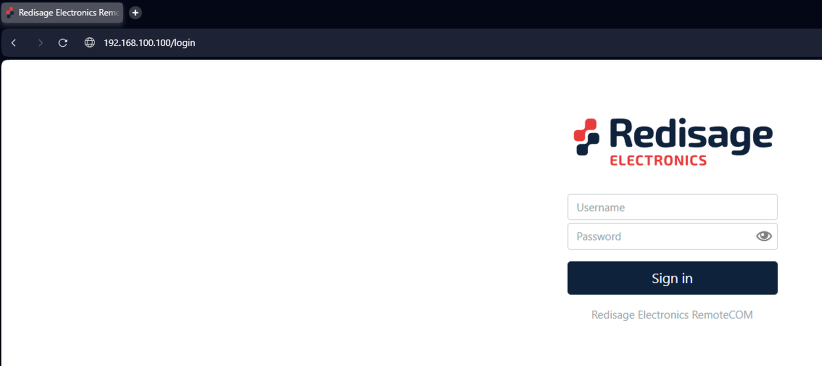](https://doc.redisage.com/uploads/images/gallery/2025-03/1vpimage.png)The configuration is available only if devices are connected to the same Local Area Network as the computer used for it.
### Status page After a successful login, there should be an insight to important information such as: port status, service and ports which are in use and other details about the connection. [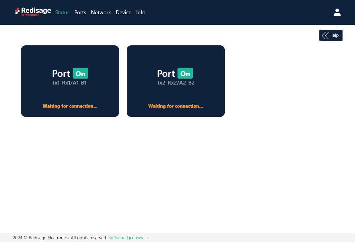](https://doc.redisage.com/uploads/images/gallery/2024-03/621a9445-3b44-42ec-b18b-2dd9f1ff95ef.png) #### Changing username or password After clicking “Edit User” under the user icon, it is possible to change the username or the password. [](https://doc.redisage.com/uploads/images/gallery/2024-03/60a6ddcb-65d2-48f6-a471-9eaebc1f75bf.png) [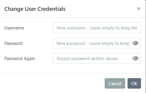](https://doc.redisage.com/uploads/images/gallery/2024-03/08cea4a8-e1e1-4241-a0ea-bf987363d2b7.png)If login details were forgotten, it would be necessary to do a factory reset via a USB/UART converter and a serial console.
### Ports page This page allows to configure the device’s ports. There is a toggle switch next to the “Port” label by which it is possible to turn ON/OFF any particular ports. [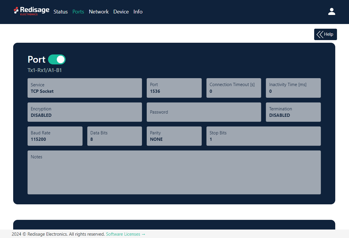](https://doc.redisage.com/uploads/images/gallery/2024-03/99bb0679-5937-4fb6-b6f5-59e8d0b89d74.png) [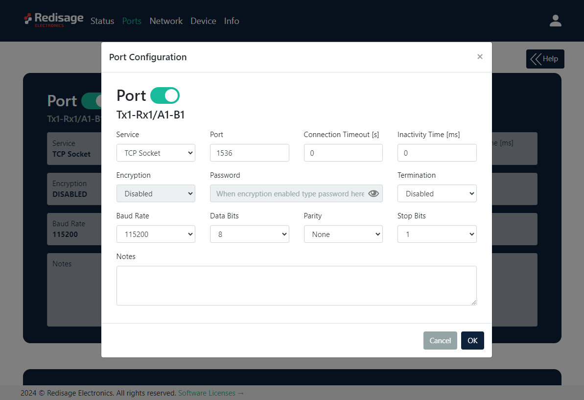](https://doc.redisage.com/uploads/images/gallery/2024-03/762f162a-1c33-4674-8f6f-827edb003235.png) {{@170#bkmrk-item-description-ser}}Changing port’s service closes all sockets connected to the ports.
In the UDP mode, port number 15051 is reserved for UDP broadcast service.
### Network page In this section, network settings can be changed according to target LAN parameters. [](https://doc.redisage.com/uploads/images/gallery/2024-03/8386aa9b-6add-432d-945d-303e590ed269.png) [](https://doc.redisage.com/uploads/images/gallery/2024-03/98a9fcdf-9549-4d9a-9e04-ef90021cfaff.png) {{@170#bkmrk-item-description-con}} [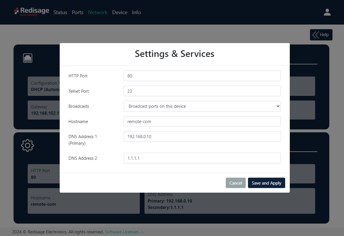](https://doc.redisage.com/uploads/images/gallery/2024-03/e3574681-36ef-4fdb-8979-97046c2c7d5d.png) {{@170#bkmrk-item-description-htt}} It is possible to obtain a dynamic IP address. Just switch configuration method from static IP to DHCP (automatic). This process may cause some issues with identifying converters in LAN unless there is an access to the device which is responsible for allocating IP addresses. Keep in mind that in case of changed IP address user needs to type a new IP in the address bar and log in again. ### Device page On the device page there are tools used to a firmware update, a factory reset and a device reboot. [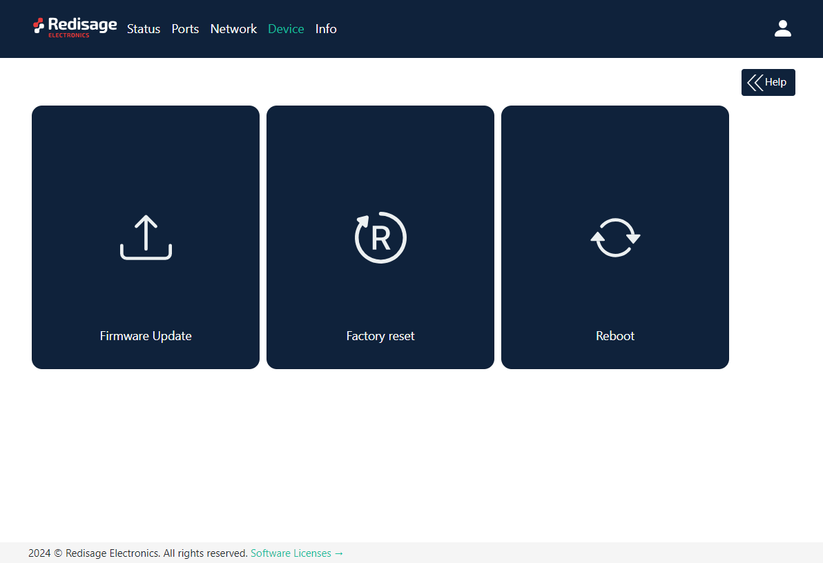](https://doc.redisage.com/uploads/images/gallery/2024-03/744e0c74-d7cf-43f3-a024-fa06e1bd9fc2.png) {{@170#bkmrk-item-description-fir}} #### Firmware update The device firmware update must not be interrupted. Update the device only if experiencing issues, being instructed to do so by our support or requiring the latest features/bugfixes. Failure during the update may 'brick' the device and make it unusable. [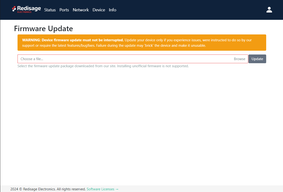](https://doc.redisage.com/uploads/images/gallery/2024-03/71859a06-2f70-4920-be81-0d60bb5e451e.png)Use the **wire-city-esp32.fir** file for a firmware update.
#### Factory reset To restore default settings, press the “Factory Reset” button. After that, user will be asked to type “RESET”. Then it will take a few seconds to reload the web page and restart the device. After the reset use default login details (login: **admin**, password: **admin123**; default IP**: 192.168.100.100**). [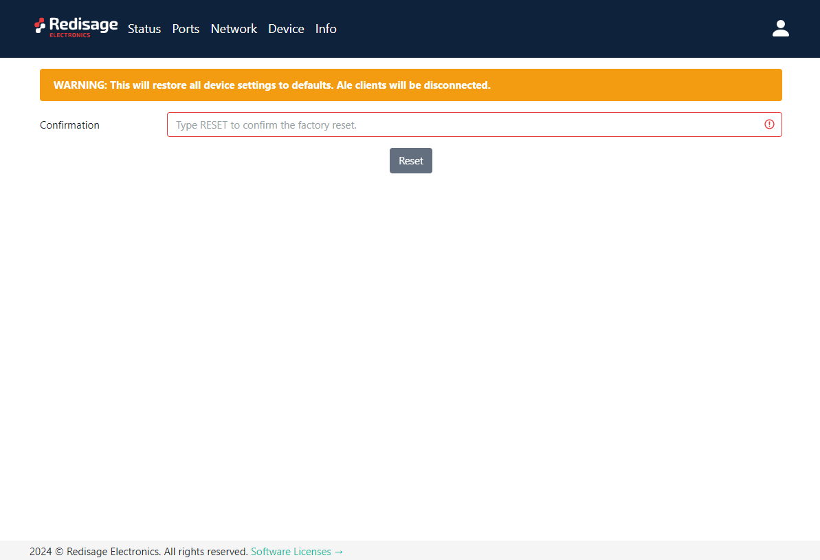](https://doc.redisage.com/uploads/images/gallery/2024-03/c9d4ee5e-9727-4033-9a9f-12538328efb2.png) #### Info page This page contains basic information about the device. [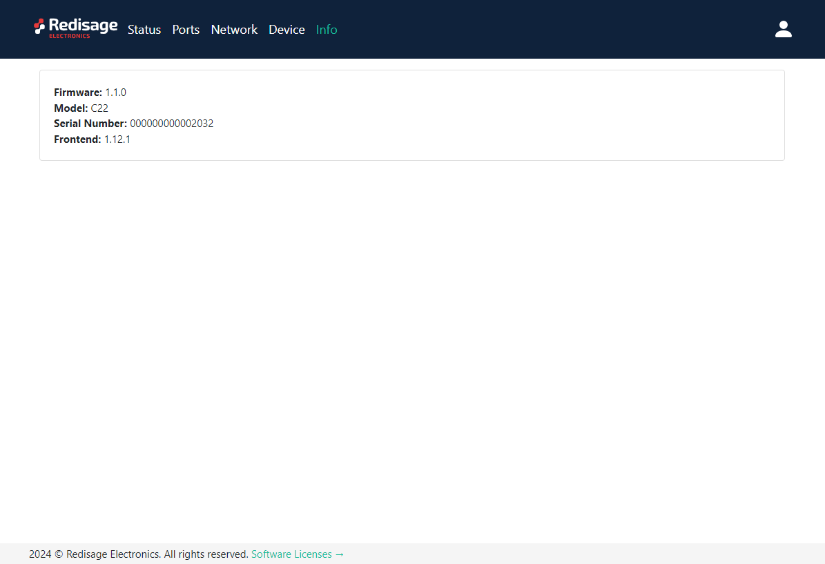](https://doc.redisage.com/uploads/images/gallery/2024-03/1a9460c1-8535-4837-9f71-c1b91c86eece.png) # Configuration by the Telnet Console ## {{@174#bkmrk-remotecom-%28c20---c25}} The device can be also configured via the Telnet Console. Firstly, make sure that converter is connected to the power supply and to the LAN using a patch cord. Knowledge of the device’s IP address (default is **192.168.100.100**) and Telnet port number (default is **23**) is necessary to establish a connection. Use command below in a terminal window to connect to the device: ```bash telnetThe configuration is available only if devices are connected to the same Local Area Network as the computer used for it.
### {{@170#bkmrk-list-of-all-commands}} {{@170#bkmrk-command-description-}} {{@171}} ### Additional notes After some time of inactivity, session will be disconnected automatically. In order to avoid issues like connecting to the host, type “help” to get more information. To get more details about every particular command, append “help” after each commands (example: "ipconfig help"). Factory reset is not available from the Telnet Console level. # Configuration by the Serial Console ## {{@174#bkmrk-remotecom-%28c20---c25}} Another way to configure the device is via a serial console. In case of the C20 - C22 Ethernet Converters an additional USB/UART converter is needed. ##### {{@173#bkmrk-procedure-to-enter-s}} {{@173#bkmrk-turn-off-the-power-o}} ##### {{@173#bkmrk-procedure-to-enter-s-1}} {{@173#bkmrk-install-stm32-virtua}} [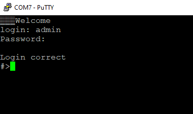](https://doc.redisage.com/uploads/images/gallery/2024-03/a5a95447-11ad-467f-afc0-dd83c392aa44.png) ### {{@170#bkmrk-list-of-all-commands}} {{@170#bkmrk-command-description-}} {{@171}} ### Service mode #### {{@173#bkmrk-procedure-to-enter-s-2}} {{@173#bkmrk-turn-off-the-power-o-1}} #### {{@173#bkmrk-procedure-to-enter-s-3}} {{@173#bkmrk-install-stm32-virtua-1}} #### {{@170#bkmrk-list-of-commands-in-}} {{@170#bkmrk-command-description--1}}{{@170#bkmrk-in-the-service-mode%2C}}
##### Factory reset To restore default settings, type “defaults”. After that, user will be asked to type “default network” to reset the network settings as well. Then user will be informed if the process is successful. Default login details: \- login: **admin** \- password: **admin123** \- IP: **192.168.100.100** ### Additional notes In order to avoid issues like connecting to host, type “help” to get more information. To get more details about every particular command, append “help” after each commands (example: "ipconfig help"). # Redisage Configurator ## {{@174#bkmrk-remotecom-%28c20---c25}} Redisage Configurator is an app used to emulate connection between converter and a PC as if its RS232/RS485 ports would be connected directly to the COM port. The advantage of that functionality is lack of additional cables. Transmission can be tested over Ethernet. First connect the device to a local network using the Ethernet port and power it up. During the configuration process set “Service” to the RemoteCOM option on the “Ports” page.While changing port service from RemoteCOM to TCP/UDP Socket make sure to disable RemoteCOM virtual port in the Redisage Configurator first.
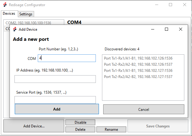
[](https://doc.redisage.com/uploads/images/gallery/2024-03/695bda65-74cf-4695-b478-e42bbd95c617.png) ### Redisage VSP Driver In order for Redisage Configurator to work properly, it is necessary to install the Redisage VSP Driver. It can be done with RedisageVSPDriver.Installer available for Windows. [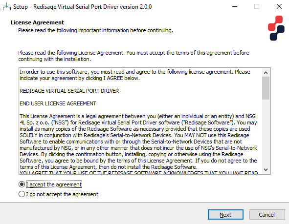](https://doc.redisage.com/uploads/images/gallery/2024-03/4e06a5a0-4a26-4fb3-b676-8b6d856b08d2.png) ### Redisage Configurator When the device is configured open the Redisage Configurator app. [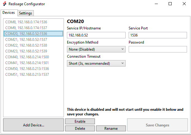](https://doc.redisage.com/uploads/images/gallery/2024-03/11350c46-7007-4fcb-add1-062c5c31ef21.png) Use the “Add Device” button to set up a new connection with a device. On the right side there should be a list of available devices visible. Choose one of them or specify a custom COM port number, an IP address and a service port number.While specifying a custom virtual COM make sure to use the same IP address and service port as set earlier in the port configuration.
[](https://doc.redisage.com/uploads/images/gallery/2024-03/7d9e3ea8-6904-4f6d-b072-47b15c80d60c.png) In order to establish a connection with a desired device use the “Enable” button. To end the connection use the “Disable” button. Service IP/hostname, service port and password can be modified at any time. There are also available 2 options of the encryption methods (none (disabled) or strong (AES-GCM 128-bit, Argon2)) and 5 options of the connection timeout (brief, short, fair, modest or lengthy). Changes have to be saved with “Save Changes” button. [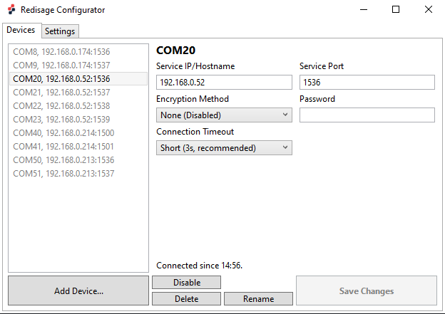](https://doc.redisage.com/uploads/images/gallery/2024-03/434ace32-b439-47be-b821-da79cef2b770.png) There is also the “Settings” tab at the top of the window from where the Logging Directory or the Device Manager can be opened. [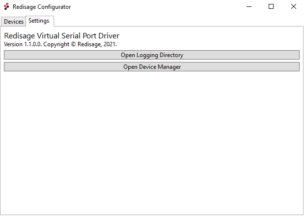](https://doc.redisage.com/uploads/images/gallery/2024-03/ae6fd1d6-457d-4da4-82bc-99785acd103f.png) If everything is connected properly there should be a new COM port available in the Device Manager. It is also possible to check it, for example, on the web page.If any change is made to the port configuration, make sure to apply it with the “Save Changes” button.
### Troubleshooting If a discovered device cannot be added, check if it hadn’t been added before with a different COM port / service port. In that case, delete previous configuration from the Redisage Configurator. If that won’t work, check if the port service was configured correctly for the RemoteCOM Service. # FAQ ## {{@174#bkmrk-remotecom-%28c20---c25}} ### How to obtain an IP address of the device? The default static IP address of the device is **192.168.100.100**. However, if the DHCP option is set, it will be necessary to obtain the IP address from a local network. First of all, connect the device to the local network (for example via a network switch). The easiest way to find the IP address of the device is via the Serial Console. After a successful login use “ipconfig” command to print all the information about the Ethernet connection. The IP address should be shown there. ### How to recover an access to the device after the password was lost? The only option to reset the user’s password is to do a hard reset via the service mode in the Service Console. To restore default settings, including login and password, type “defaults” in the terminal. Now the default credentials are: - login: **admin** - password: **admin123** ### I cannot set up the virtual COM through the Redisage Configurator app. What should I do? If in the Redisage Configurator a discovered device cannot be added, check if it hadn’t been added before with a different COM port / service port. In that case, delete previous configuration from the Redisage Configurator. If that won’t work, check if the port service was configured correctly for the RemoteCOM Service. ### How to check if the device is configured correctly? The device’s status can be checked on the “Status” page of the configuration website. If a connection with the device is established, there should be a corresponded label visible (“Server is starting…”, “Waiting for connection” or “Client connected!”). # Modes of Operation RemoteCOM (C20 - C25) # TCP Socket Mode ## {{@174#bkmrk-remotecom-%28c20---c25}} This article presents a simple instruction of a first connection between a TCP client and a RS232/485 device through the RemoteCOM. Firstly, connect the RemoteCOM according to the diagram below.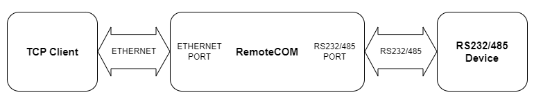
If a discovered device cannot be added, check if it hadn’t been added before with a different COM port / service port. In that case, delete previous configuration from the Redisage Configurator.
If that won’t work, check if the port service was configured correctly for the RemoteCOM Service.
Enable the virtual COM port with the “Save changes” button. If a password was set during the configuration, it will be necessary to type it into the “Password” field. [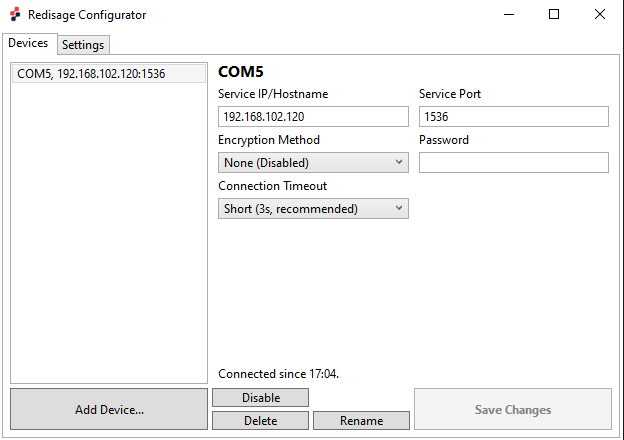](https://doc.redisage.com/uploads/images/gallery/2024-03/e19b5421-ac8b-4550-a294-483993959714.png) Now, the device should be ready to work. The bidirectional communication should be available from the start. It is possible to check if created virtual COM port is present in the system. Just go to the “Settings” page and choose “Open Device Manager” button. There should be a “Redisage” COM visible. [](https://doc.redisage.com/uploads/images/gallery/2024-03/ae6fd1d6-457d-4da4-82bc-99785acd103f.png) [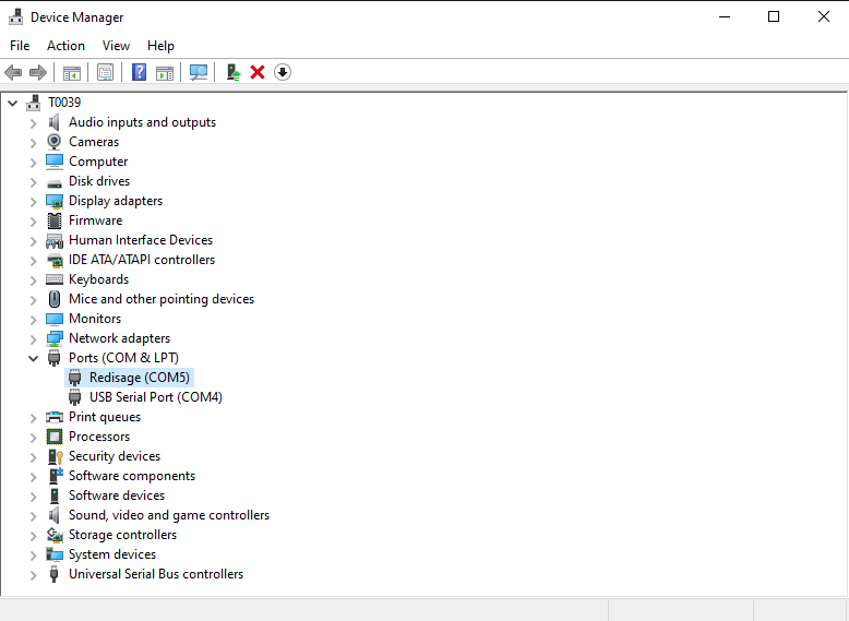](https://doc.redisage.com/uploads/images/gallery/2024-03/020d37e6-2e08-489b-8ee5-ee3b9dc9ecad.png) ### Test connection Connection can be easily tested with a USB-RS232/485 converter and [Hercules Setup Utility](https://www.hw-group.com/software/hercules-setup-utility) software. Connect the RemoteCOM’s RS232/485 port to the USB-RS232/485 converter and plug it in to a USB port of a PC. Open 2 instances of Hercules Setup Utility program and go to the “Serial” page of the first one. Set serial connection options according to the previous RemoteCOM’s ports configuration and open the COM port (fixed options: Baud Rate 115200; Data Bits: 8; Parity: None; Stop Bits: 1). Then, go to the “Serial” page of the second Hercules instance and set the virtual COM port in the same way as the serial port of the first Hercules instance. After a successful connection, there should be the bidirectional communication available. [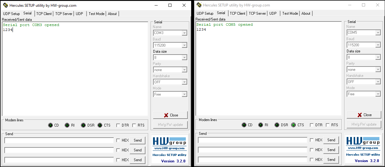](https://doc.redisage.com/uploads/images/gallery/2024-03/4bc9a829-b72c-4178-9877-26c1a60616e6.png)While changing port service back from RemoteCOM to TCP/UDP Socket make sure to disable RemoteCOM virtual port in the Redisage Configurator first.
# Contact Us - [Main web page](https://redisage.com/) - [Facebook](https://www.facebook.com/Redisage/) - E-mail:| **Redisage PN** | **C20** | **C21** | **C22** | **C23** | **C24** | **C25** | |
| Ports | RS232 | 2x | - | - | 4x | - | 2x |
| RS485 | - | 1x | - | - | 4x | 2x | |
| RS232/RS485 | - | - | 2x | - | - | - | |
| Microcontroller | ESP32 | STM32F4 | |||||
| WiFi | N/A | ||||||
| Power | Voltage | 12-30 VDC | |||||
| Power | < 1 W | ||||||
| Frame ground connection | yes | ||||||
| Baud rate | up to 115200 bps | ||||||
| LED indicators | communication Tx, Rx and power | ||||||
| RS485 termination | 120 ohm manually enabled | ||||||
| Connector | RS232/RS485 | 8-pin terminal block max. 2.5 mm2 wire | |||||
| Power | 3-pin terminal block max. 2.5 mm2 wire | ||||||
| Ethernet | RJ45 | ||||||
| Transmission distance | RS485 | max. 1,200 m at 9.6 kbps; max. 400 m at 115.2 kbps (Belden 9841 2P twisted-pair cable, if different cables are used, the transmission distance may change) | |||||
| RS232 | max. 15 m at 115.2 kbps | ||||||
| Mounting and enclosure | DIN rail, plastic PA - UL 94 V0, black/green | ||||||
| Temperatures | -40°C to +75°C operating and storage | ||||||
| Humidity | 10 - 90% RH, non-condensing | ||||||
| ESD protection | ±4 kV contact discharge / ±8 kV air discharge | ||||||
| Certification | CE, RoHS, EMC, LVD | ||||||
| Norms | 61000-6-2 - Immunity standard for industrial environments 61000-6-4 - Emission standard for industrial environments | ||||||
| **C20** [](https://doc.redisage.com/uploads/images/gallery/2024-03/cb11de82-9b9c-441b-a5ec-a154b2974af1.png) | **C21** **[](https://doc.redisage.com/uploads/images/gallery/2024-03/9ec3cdd8-81fa-43f3-b5d6-321d3e380273.jpg)** |
| **C22** **[](https://doc.redisage.com/uploads/images/gallery/2024-03/b256a7e1-4bcb-44a8-8d61-d9973cc82d4e.png)** | **C23** **[](https://doc.redisage.com/uploads/images/gallery/2024-03/c0d89b16-0d72-4553-aacd-745659a94c87.png)** |
| **C24** **[](https://doc.redisage.com/uploads/images/gallery/2024-03/939889bb-f557-4d08-b093-d2ac790a3bce.png)** | **C25** [](https://doc.redisage.com/uploads/images/gallery/2024-03/46bb1368-b158-4f8d-8114-304a359a9685.png) |
| **Item** | **Description** | |
| Service | RemoteCOM | The RemoteCOM option lets to attach the port to a computer running the [Redisage Configurator](https://doc.redisage.com/books/remotecom/page/redisage-configurator "Redisage Configurator") as if it would be physically present in the computer. |
| TCP Socket | TCP/UDP Socket exposes this port as a regular network socket - connect to this socket with own software and write/read data to send/receive data over the serial port without any additional software or serial port handling. | |
| UDP Socket | ||
| Port | The service number - the device has an “IP Address” by which it is identified and a couple of services running on it. It's required to tell the device which service should be in use by entering this device's IP address and the port number in the RemoteCOM client or user’s software. | |
| Connection Timeout \[s\] | The time specifying how often (every how many seconds) the "keep alive" packet will be sent to check if the client is still connected. Value 0 means that the connection is kept permanently without any timeout. | |
| Inactivity Time \[ms\] | The maximum allowed time in milliseconds during which there is no data transfer. When connection is inactive for the time longer or equal to the entered value, then it will be closed. Value 0 means there is no measure of the inactivity time at all. | |
| Encryption | Determine how the data is protected 'in flight' over a network. It is available only with the RemoteCOM service. Once enabled, it is necessary to set the password. | |
| Password | Protect the communication between the device and various clients - keep it secret! Same settings have to appear in clients - without the correct passwords, a client will not be able to connect at all. | |
| Termination | Enable/disable termination on the RS line. | |
| Baud Rate | Determine the port's transmission speed over the data channel. | |
| Data Bits | Determine the number of data bits in the port's message frame. | |
| Parity | Enable/disable parity check in the port's message frame. | |
| Stop Bits | Determine the number of stop bits in the port's message frame. | |
| Notes | These notes are for information only - feel free to write down anything related to this port (device it connects to, etc.). They're also shown in the Configurator during the device discovery - in the other words, they're public. | |
| **Item** | **Description** |
| Configuration Method | Enable/disable the DHCP server. If the DHCP server is disabled, the IP address of the device has to be set manually. |
| IP Address | IP address of the device. |
| Netmask | Netmask associated with the IP address. |
| Gateway | Gateway address currently used by the device. |
| MAC Settings | Allow setting the default MAC address or typing it manually. |
| MAC Address | Allow changing the physical address of the device. |
| **Item** | **Description** |
| HTTP Port | Determine the port of the control panel. |
| Telnet Port | Allow connection with the device via Telnet. |
| Broadcasts | Notify RemoteCOM clients in the same network about this device's existence. With this enabled, the Configurator will automatically set most of the settings correctly after picking the correct port. |
| Hostname | Label that is assigned to the device. |
| DNS Address 1 (Primary) | Primary Domain Name System used by the device. |
| DNS Address 2 | Domain Name System used by the device. |
| **Item** | **Description** |
| Firmware Update | Update firmware. |
| Factory Reset | Restore default ports settings and default network configuration. |
| Reboot | Reboot the device. |
| **Command** | **Description** |
| help | Print the help. |
| conn | Print active TCP connections. |
| eth\_mac | Print or change MAC address. |
| exit | Close current CLI session. |
| http\_port | Print or change default http port. |
| ipconfig | Print or change the network configuration. |
| net\_stat | Print lwIP statistics. |
| ping | Check internet connection with the desired host. |
| restart | Restart the system. |
| reboot | Same as restart. |
| sys\_heap\_usage | Print current heap usage. |
| telnet\_port | Print or change default telnet port. |
| uart | Print or change uart configuration. |
| uart\_service | Print or change uart\_service configuration. |
| user | Print or change user configuration. |
| **Command** | **Description** |
| help | Print the help. |
| credits | Print current credits value for this device. |
| dev\_ident | Print the device identification value. |
| restart | Restart the system. |
| serial\_num | Print the serial number of this device. |
| version | Display the bootloader version. |
| xmodem | Download image to the internal flash using xmodem. |
| defaults | Reset application variables to defaults. |
| ipconfig | Print or change the network configuration. |
| flash\_read | Read bytes from flash memory. |
| md | Read bytes from memory address. |
In the service mode, the “ipconfig” command can only show a last static IP address.
# Commands ##### Ports configuration commands In terms of ports configuration it is possible to change parameters like: service, baud rate, data bits, parity, stop bits and so on. UART commands are provided below. - **uart** - **uart help** Print the help message. - **uart list** List available uarts in the system. Example: uart list 0: baud: 9600 bits: 8 stop\_bits: 1 parity: none (service console) 1: baud: 115200 bits: 8 stop\_bits: 2 parity: odd (covered by cons.) 2: baud: 9600 bits: 8 stop\_bits: 1 parity: none 3: baud: 1200 bits: 8 stop\_bits: 2 parity: even termination: ON (R-COM) 3: baud: 38400 bits: 8 stop\_bits: 2 parity: none termination: OFF - **uart PORT\_NUMBER baud BAUD** Set PORT\_NUMBER baudrate to BAUD. BAUD value can be one of the following: 2400, 4800, 9600, 14400, 19200, 38400, 57600, 115200. Example: uart 1 baud 9600 WARNING: UART covered by console. Changes will take place after the reset. - **uart PORT\_NUMBER bits BITS** Set bit length to BITS. BITS value can be one only 8. Example: uart 2 bits 8 - **uart PORT\_NUMBER stop\_bits STOP\_BITS** Set stop\_bits length to STOP\_BITS. STOP\_BITS value can be only 1 or 2. Example: uart 2 stop\_bits 1 - **uart PORT\_NUMBER parity PARITY** Set uart parity to PARITY. PARITY value can be one of the following: none, odd, even. Example: uart 3 parity even - **uart PORT\_NUMBER termination STATE** Set uart termination to new STATE. STATE can be only ON or OFF. Example: uart 3 termination ON - **uart\_service** - - **uart\_service help** Print the help message. - **uart\_service list** List of uarts services status. Example: uart\_service list 1 state: ON service: Remote COM port: 1504 enc: YES 2 state: OFF service: TCP Socket port: 1510 3 state: OFF service: UDP Socket port: 1510 - **uart\_service UART\_NUMBER state STATE** Set UART\_NUMBER state to STATE. STATE value can be only ON or OFF. Example: uart\_service 1 state ON - **uart\_service UART\_NUMBER service SERVICE** Set UART\_NUMBER service to SERVICE. SERVICE value can be one of the following: Remote COM, TCP Socket, UDP Socket. Example: uart\_service 1 service TCP Socket - **uart\_service UART\_NUMBER port PORT\_NUMBER** Set UART\_NUMBER port to PORT\_NUMBER. PORT\_NUMBER value can be any in the range: 1-65535. Example: uart\_service 1 port 1501 - **uart\_service UART\_NUMBER enc ENC\_STATE** Set UART\_NUMBER encryption to ENC\_STATE. ENC\_STATE can be only YES or NO. Example: uart\_service 1 enc YES If ENC\_STATE is YES then it will ask for a new password for encryption. ##### Network settings The following commands might be helpful to change network settings according to target LAN parameters. - **ipconfig** - **ipconfig addr ADDRESS** Set IP address to ADDRESS. Example: ipconfig addr 192.168.0.10 - **ipconfig mask NETMASK** Set subnet mask to NETMASK (in dot-decimal format). Example: ipconfig mask 255.255.255.0 - **ipconfig mask BIT\_COUNT** Set subnet mask to BIT\_COUNT bits. Example: ipconfig mask 24 - **ipconfig gateway GATEWAY\_IP** Set network gateway to GATEWAY\_IP. Example: ipconfig gateway 192.168.0.1 - **ipconfig dhcp enable/disable** Enable or disable DHCP client. Example: ipconfig dhcp enable - **ipconfig dns1 ADDRESS** Set primary DNS to ADDRESS, disable getting DNS from DHCP if enabled. Example: ipconfig dns1 192.168.100.1 - **ipconfig dns2 ADDRESS** Set secondary DNS to ADDRESS, disable getting DNS from DHCP if enabled. Example: ipconfig dns2 1.1.1.1 - **eth\_mac** - **eth\_mac help** Print the help message. - **eth\_mac default** Set device’s MAC address to factory-default one. - **eth\_mac set MAC\_ADDR** Set device’s MAC address to MAC\_ADDR. Accepts both dash and colon-separated formats. Example: eth\_mac set 01-02-03-04-05-06 Example: eth\_mac set 01:02:03:04:05:06 - **http\_port** - **http\_port help** Print the help message. - **http\_port PORT\_NUMBER** Set http port to PORT\_NUMBER. A PORT\_NUMBER value must be in range: 1-65535. Example: http\_port 80 - **http\_port status** Print current http port. Example: http\_port status A current http port is 80 - **telnet\_port** - - **telnet\_port help** Print the help message. - **telnet\_port PORT\_NUMBER** Set Telnet port to PORT\_NUMBER. A PORT\_NUMBER value must be in range: 1-65535. Example: telnet\_port 23 - **telnet\_port status** Print current Telnet port. Example: telnet\_port status A current telnet port is 23 ##### Changing username or password To change username or password, use user command. Available commands: - **user help** Print the help message. - **user mod\_name USER\_NAME NEW\_NAME** Change the user name to NEW\_NAME. It fails if the name is used by another user. Example: user mod\_name admin john - **user passwd USER\_NAME** Change USER\_NAME's password. Example: user passwd admin \*\*\*\*\*\* <- here is entered password, but '\*' appears instead Note: Everyone can change the password for themselves. # Procedures ### Configuration by the Serial Console #### Procedure to enter serial console mode on C20 - C22 - Turn off the power of the device. - Connect the PC to the C1 micro-USB port of Ethernet converter using the dedicated USB/UART converter. - Open the serial console (default baud rate is 115200 bps). - Press and hold the S1 button (or connect Din pin to GND pin if the button is not mounted). - Turn on the power and wait a few seconds until the orange LED lights up. - Release the button (or disconnect Din pin from GND pin). #### Procedure to enter serial console mode on C23 - C25 - Install STM32 Virtual COM Port Driver. - Turn off the power of the device. - Connect the PC to the C1 micro-USB port using the USB cable (or use the dedicated USB/UART converter). - Open the serial console (default baud rate is 115200 bps). - Press and hold the S1 button. - Turn on the power and wait a few seconds until the yellow CN LED lights up. - Release the button (or disconnect Din pin from GND pin). ### Redisage Configurator #### Configuration procedure - Change the device port service to the RemoteCOM. - Set up a port number. - Enable or disable encryption. - If encryption is enabled create a password. - In the Redisage Configurator click add the device and then set the COM number and the service port. - If encryption is enabled enter a password. - Click save changes. - Connect to the configured serial COM port via terminal software. ### Service mode #### Procedure to enter service mode for C20 - C22 converters - Turn off the power of the device. - Connect Ethernet converter to the dedicated USB/UART converter via the microUSB port. - Connect the USB/UART converter to the PC. - Open the serial console (default baud rate is 115200 bps). - Press and hold the S1 button. - Turn on the power. - Wait until the ST indicator (red LED) lights up. - Release the S1 button. - If the process is successful, service commands can be typed into the terminal. #### Procedure to enter service mode for C23 - C25 converters - Install STM32 Virtual COM Port Driver (if it was not done before). - Turn off the power of the device. - Connect Ethernet converter directly to the PC (the dedicated USB/UART converter is not obligatory). - Open the serial console (default baud rate is 115200 bps). - Press and hold the S1 button. - Turn on the power. - Wait until the ST indicator (red LED) lights up. - Release the S1 button. - If the process is successful, service commands can be typed into the terminal. # Introduction ## RemoteCOM (C20 - C25) RemoteCOM is a complete hardware and software solution for creating remote communication ports. The software part can be uploaded to any of the Redisage C20 - C25 Ethernet Converters. It provides a communication between a LAN host and a device equipped with RS232/RS485 serial interfaces. A dedicated app makes it easy and fast to configure and deploy. There is a possibility to create virtual COM ports with the Redisage Configurator to minimize number of cables.