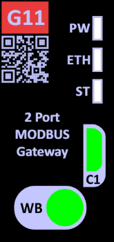
| [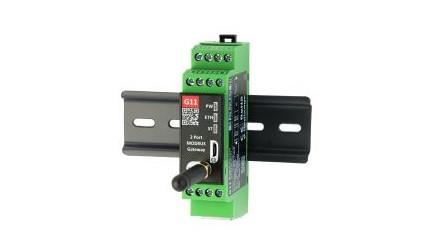](https://doc.redisage.com/uploads/images/gallery/2025-03/g11.jpg) | **Features** - 2-mode Ethernet/Wi-Fi Modbus Gateway - Ethernet/Wi-Fi converter to RS232/RS485 - ESD protection for the RS485 data line - Power supply: +12 to +30 VDC - Transmission speed up to 115200 bps - Tx, Rx and power LED indicators - RS485 embedded termination 120 ohm - Operating temperatures: -40°C to +75°C - DIN rail mounting - Dimensions: 90x56.4x22.5 mm - 3 years warranty - Customization of OEM is welcomed |
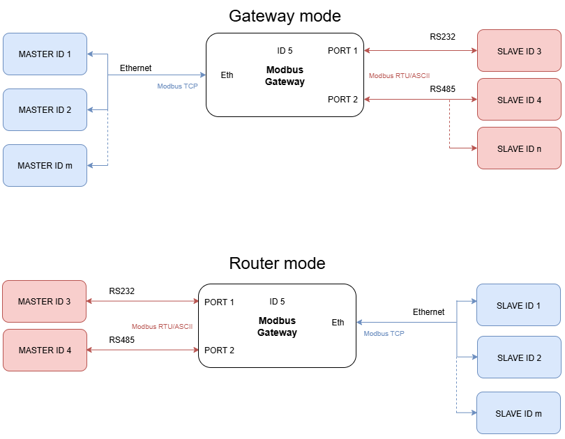
The device has max 20 sockets open in Gateway mode and max 8 in Router mode. It is possible to increase this value at client's request.
### Specification| **Redisage PN** | **G11** | **G12** | **G13** | ||||
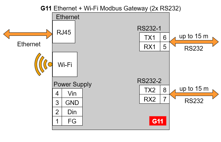
| Ports | RS232 | 2x | - | - | |||
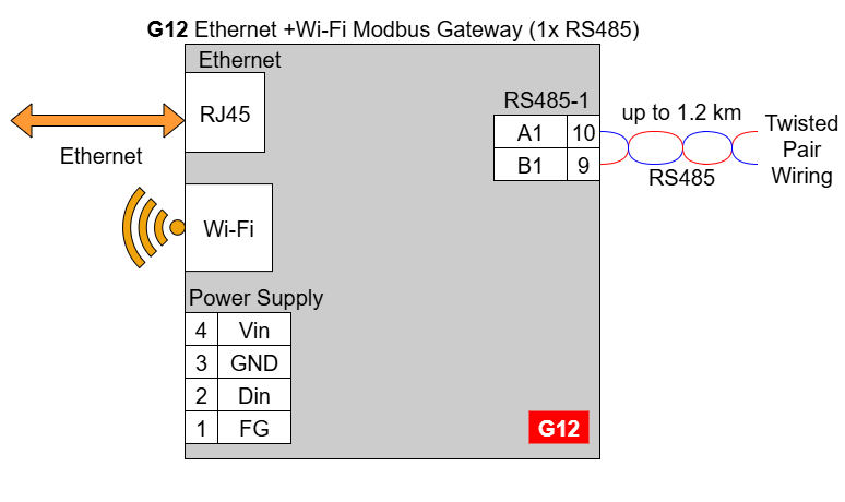
| RS485 | - | 1x | - | ||||
| RS232/RS485 | - | - | 2x | ||||
| Microcontroller | ESP32 | ||||||
| WiFi | 2.4 GHz b/g/n | ||||||
| Power | Voltage | 12-30 VDC | |||||
| Power | < 1 W | ||||||
| Frame ground connection | yes | ||||||
| Baud rate | up to 115200 bps | ||||||
| LED indicators | communication Tx, Rx and power | ||||||
| RS485 termination | 120 ohm manually enabled | ||||||
| Connector | RS232/RS485 | 8-pin terminal block max. 2.5 mm2 wire | |||||
| Power | 3-pin terminal block max. 2.5 mm2 wire | ||||||
| Ethernet | RJ45 | ||||||
| Transmission distance | RS485 | max. 1,200 m at 9.6 kbps; max. 400 m at 115.2 kbps (Belden 9841 2P twisted-pair cable, if different cables are used, the transmission distance may change) | |||||
| RS232 | max. 15 m at 115.2 kbps | ||||||
| Mounting and enclosure | DIN rail, plastic PA - UL 94 V0, black/green | ||||||
| Temperatures | -40°C to +75°C operating and storage | ||||||
| Humidity | 10 - 90% RH, non-condensing | ||||||
| ESD protection | ±4 kV contact discharge / ±8 kV air discharge | ||||||
| Certification | CE, RoHS, RED | ||||||
| Norms | 61000-6-2 - Immunity standard for industrial environments 61000-6-4 - Emission standard for industrial environments EN 300 328 – Data transmission equipment operating in the 2,4 GHz band | ||||||
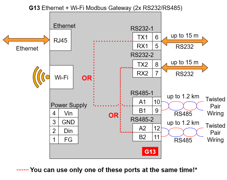
In the G13 gateway user should use only RS232 or only RS485 interface of one port as they occupy the same internal bus of the device. It means, don't use pairs: RS232-1 & RS485-1 at the same time and RS232-2 & RS485-2 at the same time!
### Frame ground FG Electronic circuits are constantly prone to electrostatic discharge ESD. Redisage Electronics modules feature a design for the frame ground terminal block FG. The frame ground provides a path for bypassing ESD, which provides enhanced static protection ESD abilities and ensures the module is more reliable. Connecting FG terminal block to the earth ground will bypass the ESD disturbances outside the device so will provide a better level of protection against ESD. Frame Ground FG connection reference drawing is provided below.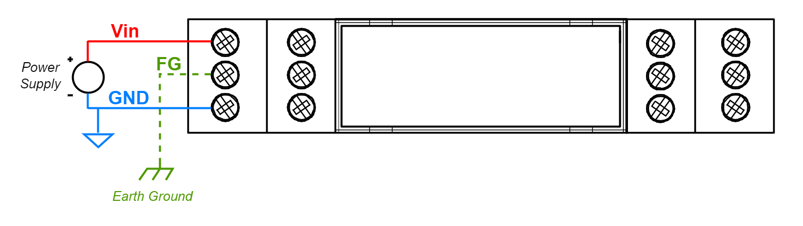
| **G11** **[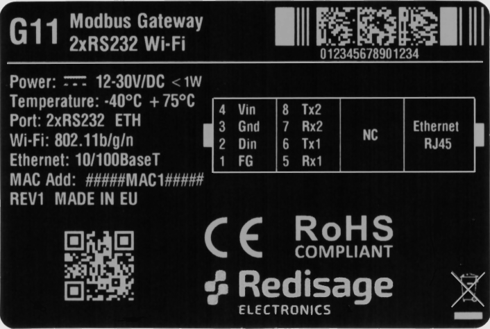](https://doc.redisage.com/uploads/images/gallery/2025-07/Vdnimage.png)** | **G12** [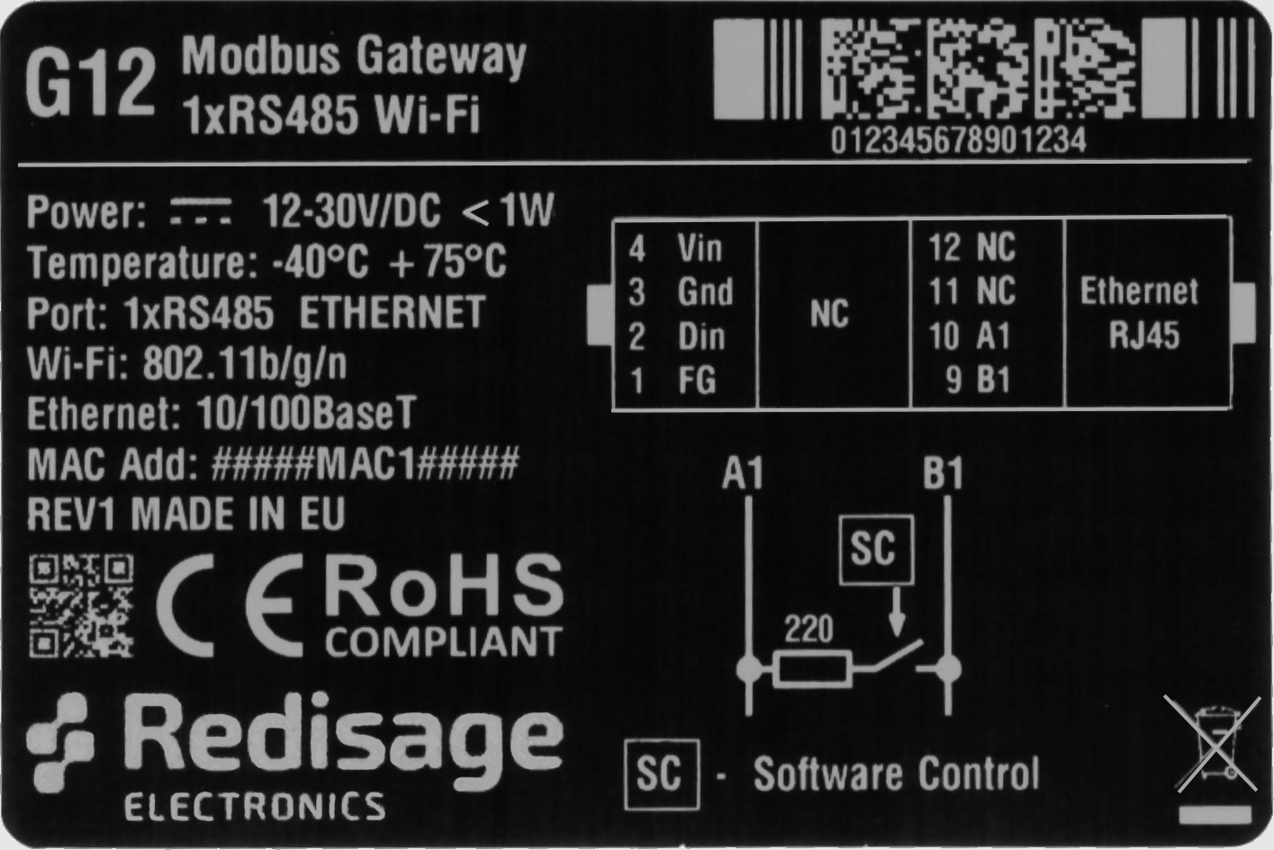](https://doc.redisage.com/uploads/images/gallery/2025-07/Xw2image.png) | **G13** [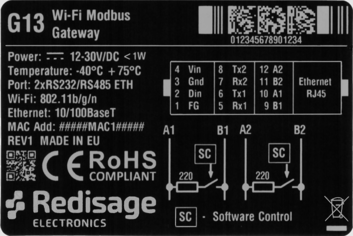](https://doc.redisage.com/uploads/images/gallery/2025-07/SN9image.png) |
| **Modbus Gateways G11 - G13** | ||
| [](https://doc.redisage.com/uploads/images/gallery/2025-07/7vEimage.png) | ||
| **LED indicator** | **Color** | **Function** |
|---|---|---|
| PW | Blue | Power |
| ETH | Green | Network activity |
| ST | Orange | Console mode |
| Red | Service mode | |