| [](https://doc.redisage.com/uploads/images/gallery/2025-09/4QZimage.png) | **Features** - 2-mode Ethernet Modbus Gateway - Ethernet converter to RS232/RS485 - ESD protection for the RS485 data line - Power supply: +12 to +30 VDC - Transmission speed up to 115200 bps - Tx, Rx and power LED indicators - RS485 embedded termination 120 ohm - Operating temperatures: -40°C to +75°C - DIN rail mounting - Dimensions: 90x56.4x22.5 mm - 3 years warranty - Customization of OEM is welcomed |
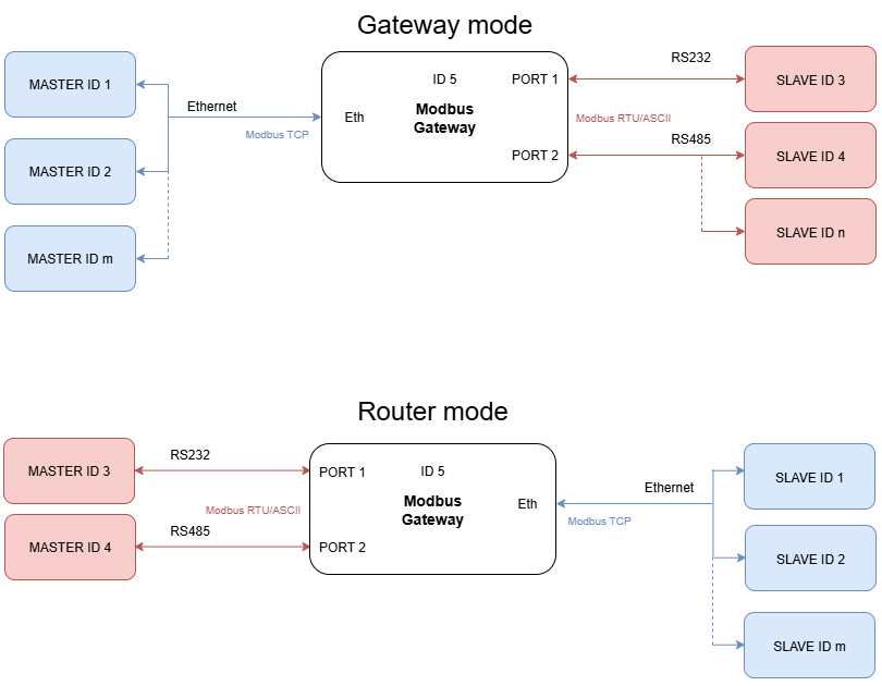
The device has max 20 sockets open in Gateway mode and max 8 in Router mode. It is possible to increase this value at client's request.
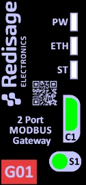
### {{@175#bkmrk-specification}} {{@175#bkmrk-redisage-pn-g01-g02-}} ### Variants #### G01 - Ethernet Modbus Gateway 2x RS232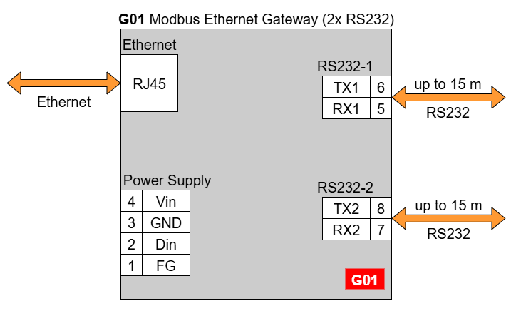
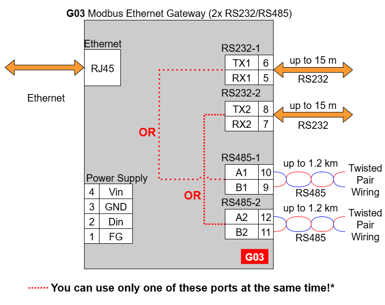
In the G03 gateway user should use only RS232 or only RS485 interface of one port as they occupy the same internal bus of the device. It means, don't use pairs: RS232-1 & RS485-1 at the same time and RS232-2 & RS485-2 at the same time!
#### G14 - Ethernet Modbus Gateway 4x RS232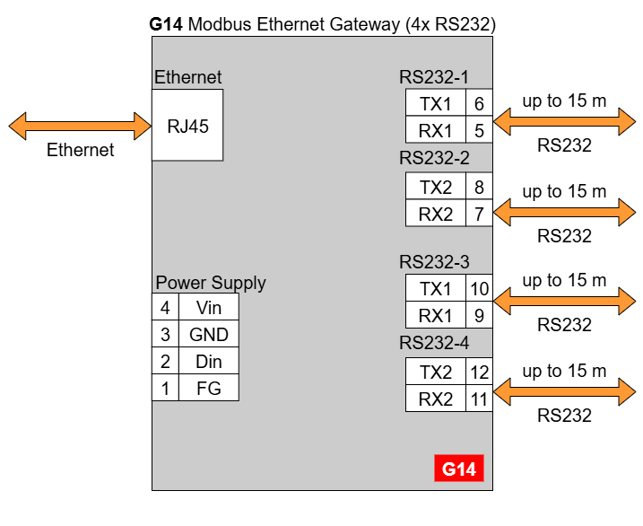
| **Modbus Gateways G01 - G03** | **Modbus Gateways G14 - G16** | ||||
| [](https://doc.redisage.com/uploads/images/gallery/2024-03/38965053-10b3-4e51-be9b-957b01b9938c.png) | [](https://doc.redisage.com/uploads/images/gallery/2024-03/fd2973ab-76ee-4878-b4ee-4b7626f6cc94.png) | ||||
| **LED indicator** | **Color** | **Function** | **LED indicator** | **Color** | **Function** |
|---|---|---|---|---|---|
| PW | Blue | Power | PW | Blue | Power |
| ETH | Green | Network activity | ETH | Green | Network activity |
| ST | Orange | Console mode | CN | Yellow | Console mode |
| Red | Service mode | COM | Green | RS232/RS485 activity | |
| SR | Red | Service mode | |||
| ER | Yellow | Error | |||