| [](https://doc.redisage.com/uploads/images/gallery/2025-09/4QZimage.png) | **Features** - 2-mode Ethernet Modbus Gateway - Ethernet converter to RS232/RS485 - ESD protection for the RS485 data line - Power supply: +12 to +30 VDC - Transmission speed up to 115200 bps - Tx, Rx and power LED indicators - RS485 embedded termination 120 ohm - Operating temperatures: -40°C to +75°C - DIN rail mounting - Dimensions: 90x56.4x22.5 mm - 3 years warranty - Customization of OEM is welcomed |
The device has max 20 sockets open in Gateway mode and max 8 in Router mode. It is possible to increase this value at client's request.
### Specification| **Redisage PN** | **G01** | **G02** | **G03** | **G14** | **G15** | **G16** | |
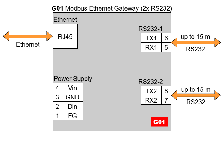
| Ports | RS232 | 2x | - | - | 4x | 2x | - |
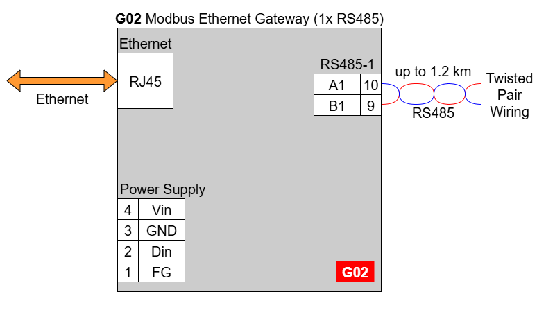
| RS485 | - | 1x | - | - | 2x | 4x | |
| RS232/RS485 | - | - | 2x | - | - | - | |
| Microcontroller | ESP32 | STM32F4 | |||||
| WiFi | N/A | ||||||
| Power | Voltage | 12-30 VDC | |||||
| Power | < 1 W | ||||||
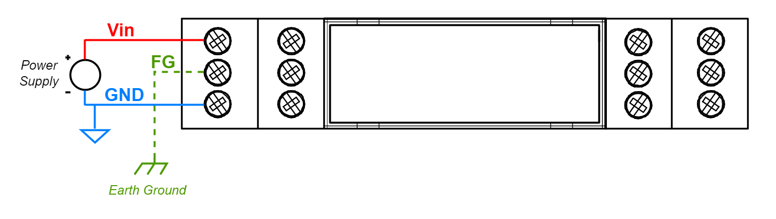
| Frame ground connection | yes | ||||||
| Baud rate | up to 115200 bps | ||||||
| LED indicators | communication Tx, Rx and power | ||||||
| RS485 termination | 120 ohm manually enabled | ||||||
| Connector | RS232/RS485 | 8-pin terminal block max. 2.5 mm2 wire | |||||
| Power | 3-pin terminal block max. 2.5 mm2 wire | ||||||
| Ethernet | RJ45 | ||||||
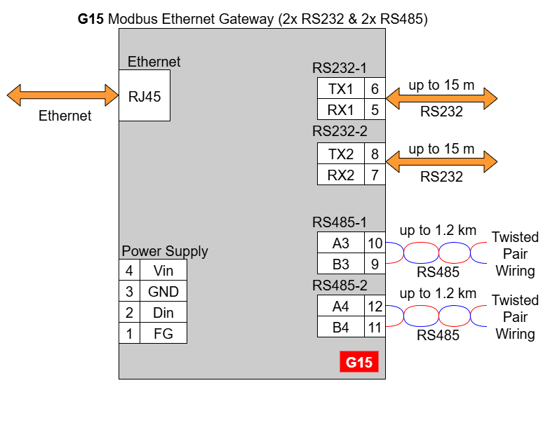
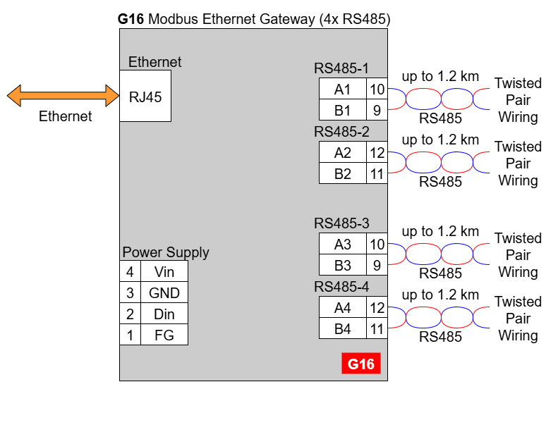
| Transmission distance | RS485 | max. 1,200 m at 9.6 kbps; max. 400 m at 115.2 kbps (Belden 9841 2P twisted-pair cable, if different cables are used, the transmission distance may change) | |||||
| RS232 | max. 15 m at 115.2 kbps | ||||||
| Mounting and enclosure | DIN rail, plastic PA - UL 94 V0, black/green | ||||||
| Temperatures | -40°C to +75°C operating and storage | ||||||
| Humidity | 10 - 90% RH, non-condensing | ||||||
| ESD protection | ±4 kV contact discharge / ±8 kV air discharge | ||||||
| Certification | CE, RoHS, EMC, LVD | ||||||
| Norms | 61000-6-2 - Immunity standard for industrial environments 61000-6-4 - Emission standard for industrial environments | ||||||
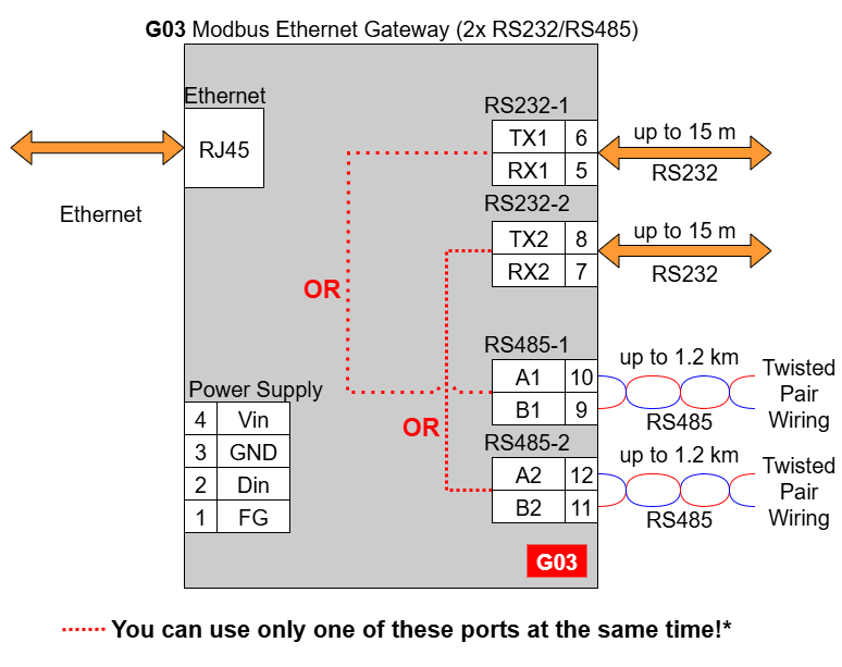
In the G03 gateway user should use only RS232 or only RS485 interface of one port as they occupy the same internal bus of the device. It means, don't use pairs: RS232-1 & RS485-1 at the same time and RS232-2 & RS485-2 at the same time!
#### G14 - Ethernet Modbus Gateway 4x RS232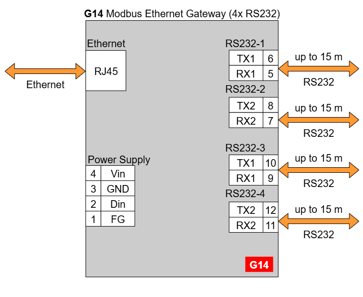
| **G01** **[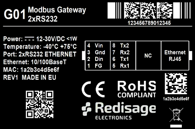](https://doc.redisage.com/uploads/images/gallery/2024-03/7a36a230-516d-413d-a5b2-aeb9c4044bb0.png)** | **G02** **[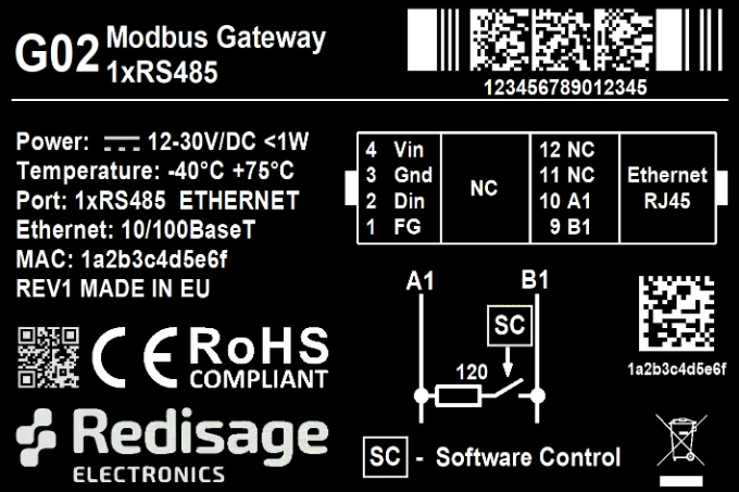](https://doc.redisage.com/uploads/images/gallery/2024-03/27b5fe0a-d8ca-451b-a20d-2f1678d04547.png)** | **G03** **[](https://doc.redisage.com/uploads/images/gallery/2024-03/54ec2665-7a15-484f-bdf2-6917b054595c.png)** |
| **G14** **[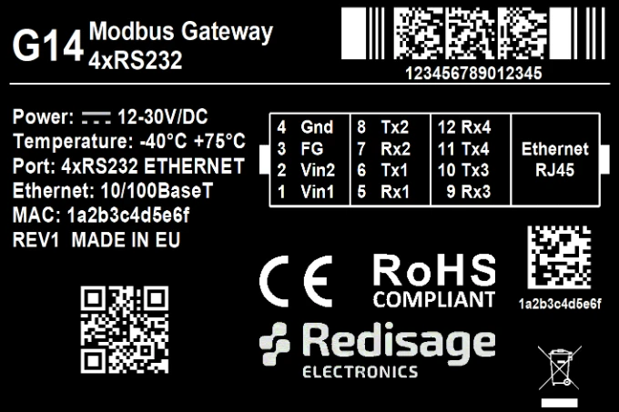](https://doc.redisage.com/uploads/images/gallery/2024-03/3194e998-4094-4387-8062-f44a1ae1bc9d.png)** | **G15** **[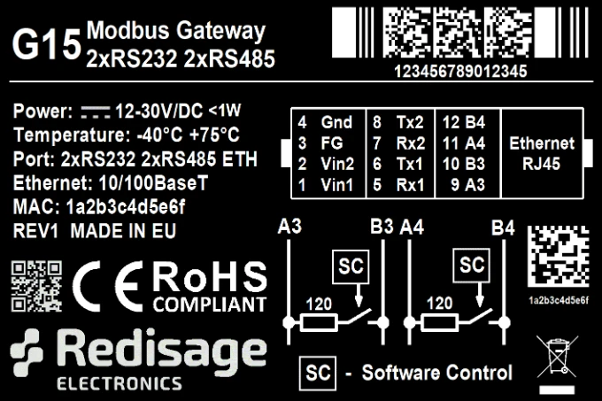](https://doc.redisage.com/uploads/images/gallery/2024-03/a9bf9b11-bebf-45e5-a3d8-81d001bb0c78.png)** | **G16** **[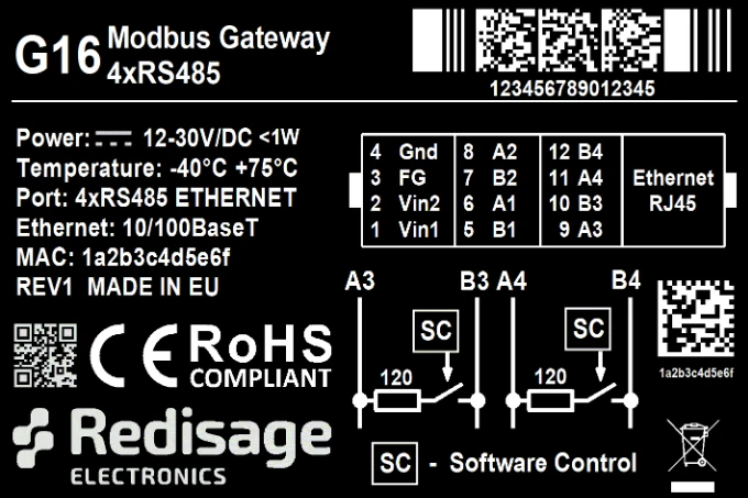](https://doc.redisage.com/uploads/images/gallery/2024-03/1bbc9a2e-ce07-44af-9ad1-3fcfe6685a3b.png)** |
| **Modbus Gateways G01 - G03** | **Modbus Gateways G14 - G16** | ||||
| [](https://doc.redisage.com/uploads/images/gallery/2024-03/38965053-10b3-4e51-be9b-957b01b9938c.png) | [](https://doc.redisage.com/uploads/images/gallery/2024-03/fd2973ab-76ee-4878-b4ee-4b7626f6cc94.png) | ||||
| **LED indicator** | **Color** | **Function** | **LED indicator** | **Color** | **Function** |
|---|---|---|---|---|---|
| PW | Blue | Power | PW | Blue | Power |
| ETH | Green | Network activity | ETH | Green | Network activity |
| ST | Orange | Console mode | CN | Yellow | Console mode |
| Red | Service mode | COM | Green | RS232/RS485 activity | |
| SR | Red | Service mode | |||
| ER | Yellow | Error | |||
| **Related information and links** | ||
| [Ordering information](https://redisage.com/en/delivery.html) | [Accessories](https://redisage.com/eng_m_Accessory-174.html) | [Similar products](https://redisage.com/search.php?text=+&sort=name&order=a) |

The configuration is available only if devices are connected to the same Local Area Network as the computer used for it.
### Status page After a successful login, there should be an insight to a list of available connections. If there is more than one connection, it is possible to sort them by ID, timestamp or status. [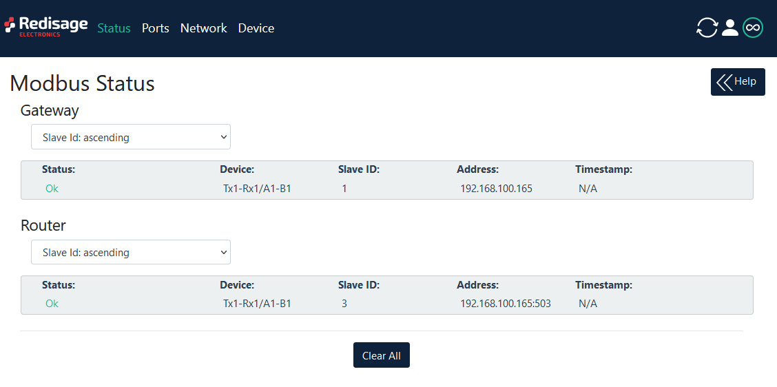](https://doc.redisage.com/uploads/images/gallery/2024-03/4f6ed827-ab6f-4372-8bef-95d723d573c8.png) #### Changing username or password After clicking “Edit User” under the user icon, it is possible to change the username or the password. [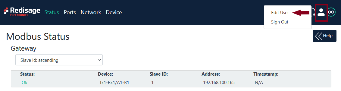](https://doc.redisage.com/uploads/images/gallery/2024-03/d0367566-ce19-4dd7-82c9-75ed8a5fb462.png) [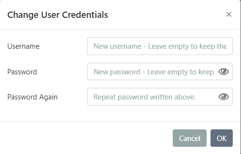](https://doc.redisage.com/uploads/images/gallery/2024-03/08cea4a8-e1e1-4241-a0ea-bf987363d2b7.png)If login details were forgotten, it would be necessary to do a factory reset via a USB/UART converter and a serial console.
### Ports configuration [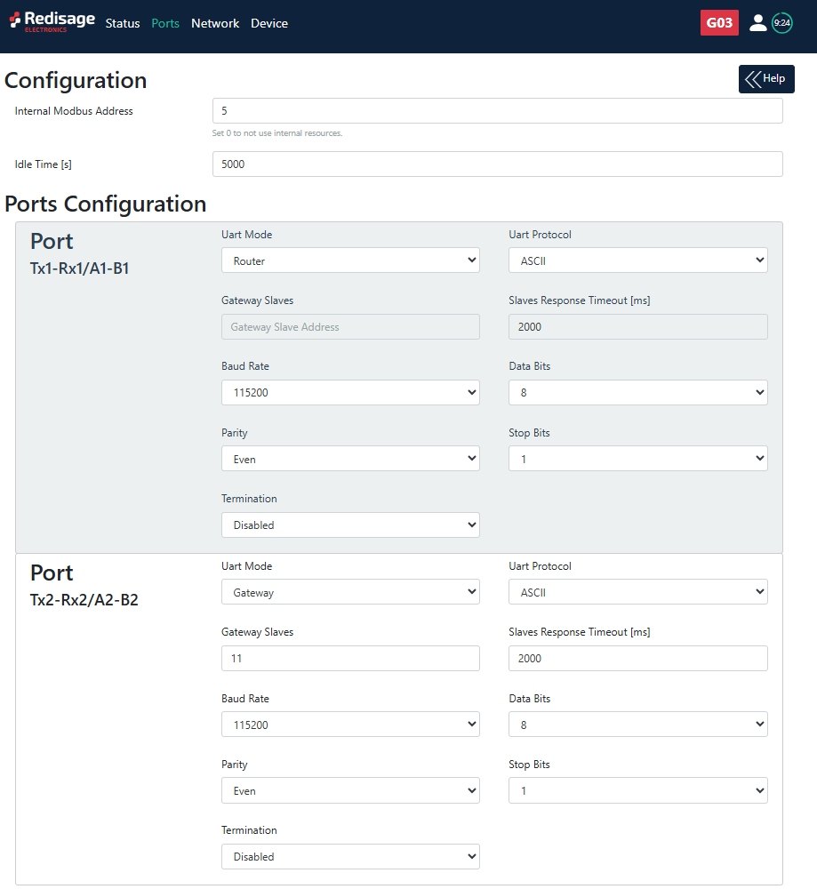](https://doc.redisage.com/uploads/images/gallery/2025-09/0Hkimage.png) [](https://doc.redisage.com/uploads/images/gallery/2025-09/gCUimage.png) [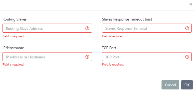](https://doc.redisage.com/uploads/images/gallery/2025-09/vabimage.png) {{@175#bkmrk-item-description-int}}Make sure to save all the changes with “Save and Apply” button located on the bottom of the page.
In the UDP mode, port number 15051 is reserved for UDP broadcast service.
### Network settings In this section, network settings can be changed according to target LAN parameters. [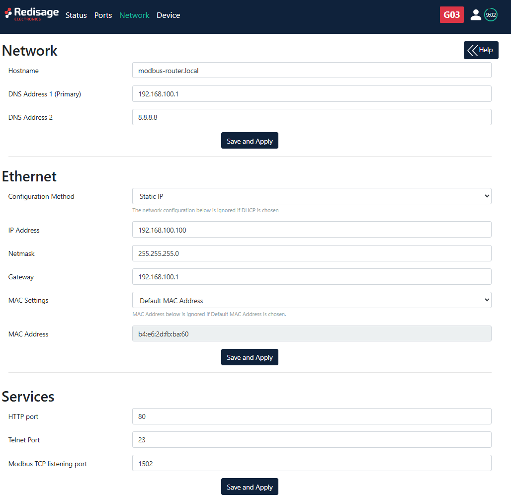](https://doc.redisage.com/uploads/images/gallery/2025-09/5ojimage.png) {{@175#bkmrk-item-description-hos}} It is possible to obtain dynamic IP address. Just switch configuration method from static IP to DHCP (automatic). This process may cause some issues with identifying converters in LAN unless there is an access to the device which is responsible for allocating IP addresses. Keep in mind that in case of changed IP address user needs to type new IP in the address bar and log in again.Make sure to save all the changes with “Save and Apply” button located on the bottom of the page.
### Device page On the device page there are tools used to a firmware update, a factory reset and a device reboot. There are also some information about the device. [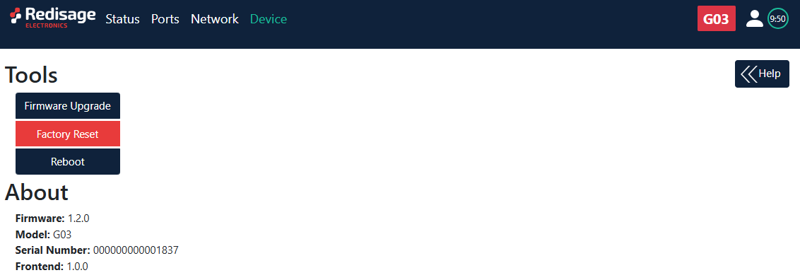](https://doc.redisage.com/uploads/images/gallery/2025-09/Kfrimage.png) {{@175#bkmrk-item-description-fir}} #### Firmware update The device firmware update must not be interrupted. Update the device only if experiencing issues, being instructed to do so by our support or requiring the latest features/bugfixes. Failure during the update may 'brick' the device and make it unusable. [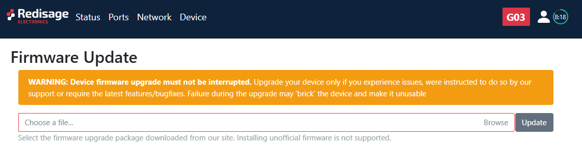](https://doc.redisage.com/uploads/images/gallery/2025-09/n7Eimage.png)Use the **modbus-gateway-mcu-esp32.fir** file for a firmware update.
#### Factory reset To restore default settings, press the red button. After that, user will be asked to type “RESET”. Then it will take a few seconds to reload the web page and restart the device. After reset use default login details (login: **admin**, password: **admin123;** default IP: **192.168.100.100**). [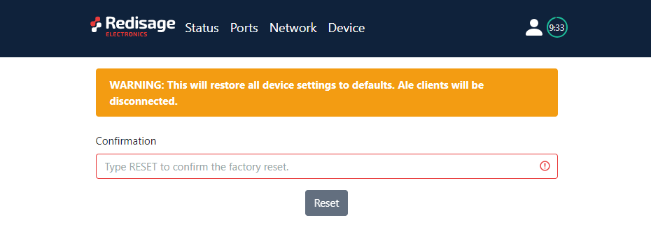](https://doc.redisage.com/uploads/images/gallery/2024-03/55a4fc0e-1fb5-4047-a4da-36cb709a988e.png) # Configuration by the Telnet Console ## {{@178#bkmrk-modbus-ethernet-gate}} The device can be also configured via the Telnet Console. Firstly, make sure that converter is connected to the power supply and to the LAN using a patch cord. Knowledge of the device’s IP address (default is **192.168.100.100**) and Telnet port number (default is **23**) is necessary to establish a connection. Use command below in a terminal window to connect to the device: ```bash telnetThe configuration is available only if devices are connected to the same Local Area Network as the computer used for it.
### {{@175#bkmrk-list-of-all-commands}} {{@175#bkmrk-command-description-}} {{@176}} ### Additional notes After some time of inactivity, session will be disconnected automatically. In order to avoid issues like connecting to host, type “help” to get more information. To get more details about every particular command, append “help” after each commands (example: "ipconfig help"). Factory reset is not available from the Telnet Console level. # Configuration by the Serial Console ## {{@178#bkmrk-modbus-ethernet-gate}} Another way to configure the device is via a serial console. In case of the G01 - G03 Modbus gateways an additional USB/UART converter is needed. ##### {{@177#bkmrk-procedure-to-enter-s}} {{@177#bkmrk-turn-off-the-power-o}} ##### {{@177#bkmrk-procedure-to-enter-s-1}} {{@177#bkmrk-install-stm32-virtua}} [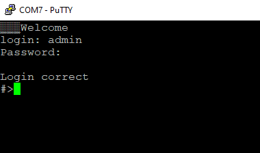](https://doc.redisage.com/uploads/images/gallery/2024-03/a5a95447-11ad-467f-afc0-dd83c392aa44.png) ### {{@175#bkmrk-list-of-all-commands}} {{@175#bkmrk-command-description-}} {{@176}} ### {{@177#bkmrk-service-mode}} ##### {{@177#bkmrk-procedure-to-enter-s-2}} {{@177#bkmrk-turn-off-the-power-o-1}} ##### {{@177#bkmrk-procedure-to-enter-s-3}} {{@177#bkmrk-install-stm32-virtua-1}} #### {{@175#bkmrk-list-of-commands-in-}} {{@175#bkmrk-command-description--1}}{{@175#bkmrk-in-the-service-mode%2C}}
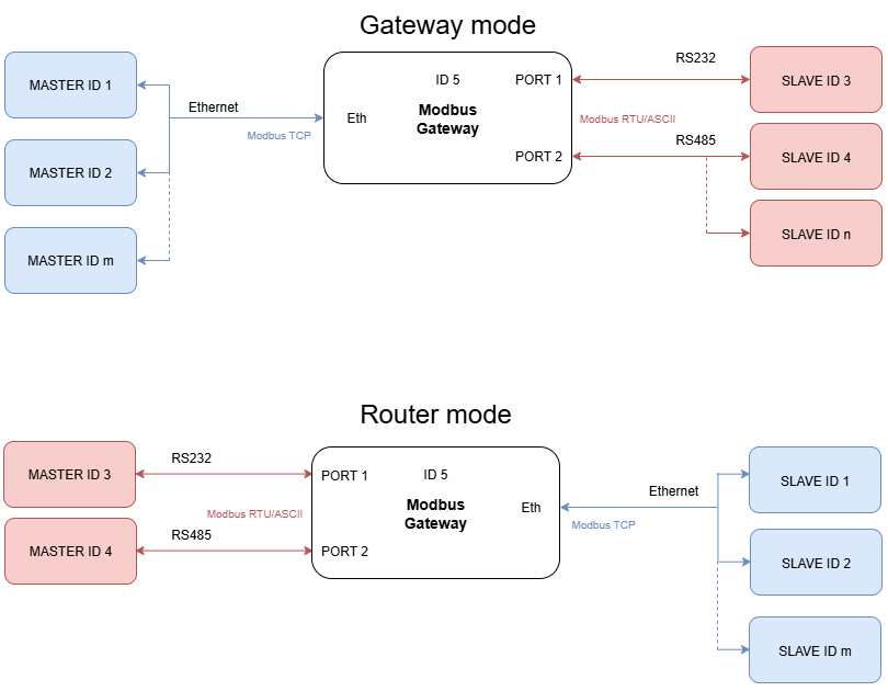
##### Factory reset To restore default settings, type “defaults”. After that, user will be asked for type “default network” to reset the network settings as well. Then user will be informed if the process is successful. Default login details: \- login: **admin** \- password: **admin123** \- IP: **192.168.100.100** ### Additional notes In order to avoid issues like connecting to host, type “help” to get more information. To get more details about every particular command, append “help” after each commands (example: "ipconfig help"). # Contact Us - [Main web page](https://redisage.com/) - [Facebook](https://www.facebook.com/Redisage/) - E-mail:| **Redisage PN** | **G01** | **G02** | **G03** | **G14** | **G15** | **G16** | |
| Ports | RS232 | 2x | - | - | 4x | 2x | - |
| RS485 | - | 1x | - | - | 2x | 4x | |
| RS232/RS485 | - | - | 2x | - | - | - | |
| Microcontroller | ESP32 | STM32F4 | |||||
| WiFi | N/A | ||||||
| Power | Voltage | 12-30 VDC | |||||
| Power | < 1 W | ||||||
| Frame ground connection | yes | ||||||
| Baud rate | up to 115200 bps | ||||||
| LED indicators | communication Tx, Rx and power | ||||||
| RS485 termination | 120 ohm manually enabled | ||||||
| Connector | RS232/RS485 | 8-pin terminal block max. 2.5 mm2 wire | |||||
| Power | 3-pin terminal block max. 2.5 mm2 wire | ||||||
| Ethernet | RJ45 | ||||||
| Transmission distance | RS485 | max. 1,200 m at 9.6 kbps; max. 400 m at 115.2 kbps (Belden 9841 2P twisted-pair cable, if different cables are used, the transmission distance may change) | |||||
| RS232 | max. 15 m at 115.2 kbps | ||||||
| Mounting and enclosure | DIN rail, plastic PA - UL 94 V0, black/green | ||||||
| Temperatures | -40°C to +75°C operating and storage | ||||||
| Humidity | 10 - 90% RH, non-condensing | ||||||
| ESD protection | ±4 kV contact discharge / ±8 kV air discharge | ||||||
| Certification | CE, RoHS, EMC, LVD | ||||||
| Norms | 61000-6-2 - Immunity standard for industrial environments 61000-6-4 - Emission standard for industrial environments | ||||||
| **G01** **[](https://doc.redisage.com/uploads/images/gallery/2024-03/7a36a230-516d-413d-a5b2-aeb9c4044bb0.png)** | **G02** **[](https://doc.redisage.com/uploads/images/gallery/2024-03/27b5fe0a-d8ca-451b-a20d-2f1678d04547.png)** | **G03** **[](https://doc.redisage.com/uploads/images/gallery/2024-03/54ec2665-7a15-484f-bdf2-6917b054595c.png)** |
| **G14** **[](https://doc.redisage.com/uploads/images/gallery/2024-03/3194e998-4094-4387-8062-f44a1ae1bc9d.png)** | **G15** **[](https://doc.redisage.com/uploads/images/gallery/2024-03/a9bf9b11-bebf-45e5-a3d8-81d001bb0c78.png)** | **G16** **[](https://doc.redisage.com/uploads/images/gallery/2024-03/1bbc9a2e-ce07-44af-9ad1-3fcfe6685a3b.png)** |
| **Item** | **Description** | |
| Internal Modbus Address | Internal Modbus Address is qualified by the Gateway/Router as a request for internal resources. The Internal Modbus Address has a higher priority than the Gateway Slave Address. | |
| Idle Time \[s\] | Determine a time thread waits for the TCP connection. If time expired, the connection and thread are closed. **Used only in Gateway Mode.** | |
| UART Mode | Gateway | Define the port's role in the system. In the Gateway Mode the port is used to communicate with Modbus Slave. |
| Router | Define the port's role in the system. In the Router Mode the port is used to communicate with Modbus Master. Note the Routing Configuration section below if the Router Mode is chosen. | |
| Disabled | Disable the port. | |
| UART Protocol | Determine a protocol used for a communication. | |
| Gateway Slaves | Addresses of Modbus Slave Devices connected to Gateway UART ports. Multiple addresses can be written in one field, e.g. *9;11;14-17;80*. This field is available only in the Gateway Mode. Use \* to select all not assigned addresses. | |
| Slaves Response Timeout \[ms\] | Specify how long the device will wait for response from Modbus Slave. | |
| Baud Rate | Determine the port's transmission speed over the data channel. | |
| Data Bits | Determine the number of data bits in the port's message frame. | |
| Parity | Enable/disable the parity check in the port's message frame. | |
| Stop Bits | Determine the number of stop bits in the port's message frame. | |
| Termination | Enable/disable termination on RS line. | |
| Routing Slaves | Addresses of Modbus Slaves connected to Modbus Router. Multiple addresses can be written in one field, e.g. 9;11;14-17;80. Use \* to select all not assigned addresses. | |
| Slaves Response Timeout \[ms\] | Specify how long the device will wait for response from Modbus Slave. | |
| IP/Hostname | Determine IP address or Hostname of Modbus Slave. | |
| TCP Port | Determine TCP port of Modbus Slave. | |
| **Item** | **Description** |
| Hostname | Label that is assigned to the device. |
| Configuration Method | Enable/disable the DHCP server. If the DHCP server is disabled, the IP address of the device has to be set manually. |
| IP Address | IP address of the device. |
| Netmask | Netmask associated with the IP address. |
| Gateway | Gateway address currently used by the device. |
| DNS Address | Domain Name System used by the device. |
| MAC Settings | Allow setting the default MAC address or typing it manually. |
| MAC Address | Allow changing the physical address of the device. |
| HTTP Port | Determine the port of the control panel. |
| Telnet Port | Allow connection with the device via Telnet. |
| Modbus TCP Listening Port | Used as an entry point for new Modbus TCP connections. |
| **Item** | **Description** |
| Firmware Update | Update firmware. |
| Factory Reset | Restore default ports settings and default network configuration. |
| Reboot | Reboot the device. |
| About | Basic information about the device. |
| **Command** | **Description** |
| help | Print the help. |
| conn | Print active TCP connections. |
| net\_stat | Print lwIP statistics. |
| eth\_mac | Print or change MAC address. |
| ipconfig | Print or change the network configuration. |
| http\_port | Print or change default http port. |
| telnet\_port | Print or change default telnet port. |
| modbus\_tcp\_port | Print or change modbus port. |
| ping | Check internet connection with the desired host. |
| restart | Restart the system. |
| user | Print or change user configuration. |
| sys\_heap\_usage | Print current heap usage. |
| modbus | Print or changes modbus settings. |
| modbus\_ports | Print or changes modbus ports settings. |
| modbus\_routing | Print or change modbus routing settings. |
| exit | Exit console. |
| **Command** | **Description** |
| help | Print the help. |
| credits | Print current credits value for this device. |
| dev\_ident | Print the device identification value. |
| restart | Restart the system. |
| serial\_num | Print the serial number of this device. |
| version | Display the bootloader version. |
| xmodem | Download image to the internal flash using xmodem. |
| defaults | Reset application variables to defaults. |
| ipconfig | Print or change the network configuration. |
In the service mode, the “ipconfig” command can only show a last static IP address.
# Commands ##### Modbus ports configuration commands - **modbus** - **modbus help** Print command help. - **modbus int\_addr VALUE** Set internal Modbus address. Example: modbus int\_addr 5 - **modbus idlet VALUE** Show or set the idle TIME (in seconds) of the TCP connection after which the TCP connection is terminated by the converter and the TCP socket is released. Example: modbus idlet 720 If a subcommand that normally sets a value is not given an argument, it will print the current value. Example: modbus idlet Set idle time is 5000 - **modbus\_ports** - **modbus\_ports help** Print command help, does not require com\_number. - **modbus\_ports PORT\_NUMBER add\_slaves \[SLAVE\_ADDR ;/- SLAVE\_ADDR, \*\]** Set all addresses of slaves connected to com\_port. A star in value means fill rest free slaves. It means all slaves that are not set to other ports will be set to this one. Example: modbus\_ports 1 addslaves 124 Example: modbus\_ports 1 addslaves 12-124 Example: modbus\_ports 1 addslaves 12;14;18 Example: modbus\_ports 1 addslaves 12;14-17;150-200 Example: modbus\_ports 1 addslaves 12;14-17;150-200, \* - **modbus\_ports PORT\_NUMBER show\_slaves** Show addresses of slaves connected to com\_port. Example: modbus\_ports 1 showslaves - **modbus\_ports PORT\_NUMBER mode \[ascii/rtu\]** Set Modbus port mode to ASCII or RTU. Example: modbus\_ports 2 mode ascii - **modbus\_ports PORT\_NUMBER baud \[RATE\]** Set the baud rate to RATE. For a list of acceptable baud rates, please refer to the manual. Example: modbus\_ports 1 baud 9600 - **modbus\_ports PORT\_NUMBER bits \[CPS\]** Set bit count to C, parity to P, and stop bits to S. Valid values are: C: 7, 8 or 9 P: N, E or O (N- none, E- even, O- odd) S: 1 or 2 Example: modbus\_ports 1 bits 8N1 Example: modbus\_ports 2 bits 7O1 - **modbus\_ports PORT\_NUMBER state \[GATEWAY/ROUTER/DISABLE\]** Enable or disable uart functionality. Example: modbus\_ports 1 state GATEWAY Example: modbus\_ports 2 state DISABLE - **modbus\_ports PORT\_NUMBER termination \[on/off\]** Enable or disable termination on RS485 port. Example: modbus\_ports 1 termination on - **modbus\_ports PORT\_NUMBER slave\_response\_timeout TIMEOUT** Set response timeout (serial slave) in ms. When this timeout expires, delayed frames are dropped. Example: modbus\_ports 1 slave\_response\_timeout 2000 If a subcommand that normally sets a value is not given an argument, it will print the current value. Example: modbus\_ports 2 baud Set baud rate is 115200PORT\_NUMBER is a number of ports in modbus gateway and it is counted from 0.
- **modbus\_routing** - **modbus\_routing help** Print routing's help. - **modbus\_routing show** Display all active routing table in system. \[LP\]: \[SLAVES NUMBERS\] \[IP/HOSTNAME\] \[PORT\] \[TIMEOUT\] - **modbus\_routing add SLAVE\_ADDR HOSTNAME PORT TIMEOUT** SLAVE\_ADDR with HOSTNAME PORT is used by uarts working in Modbus router mode. TIMEOUT (in ms) is used to close the connection if a slave is not responding. The maximum records is 8. One record for one address/ip. Example: modbus\_routing add 18 192.168.0.10 502 2000 Example: modbus\_routing add 18;25 192.168.0.10 502 2000 Example: modbus\_routing add 18-25 192.168.0.10 502 2000 Example: modbus\_routing add 18-25;\* 192.168.0.10 502 2000 Example: modbus\_routing add 18-25 modbus.local 502 2000 - **modbus\_routing remove \[HOSTNAME\_NUMBER/all\]** Remove Modbus Routing Table record. HOSTNAME\_NUMBER is line number from /show/ command. Example: modbus\_routing remove 2 Example: modbus\_routing remove all ##### Network settings The following commands might be helpful to change network settings according to target LAN parameters, - **ipconfig** - **ipconfig addr ADDRESS** Set IP address to ADDRESS. Example: ipconfig addr 192.168.0.10 - **ipconfig mask NETMASK** Set subnet mask to NETMASK (in dot-decimal format). Example: ipconfig mask 255.255.255.0 - **ipconfig mask BIT\_COUNT** Set subnet mask to BIT\_COUNT bits. Example: ipconfig mask 24 - **ipconfig gateway GATEWAY\_IP** Set network gateway to GATEWAY\_IP. Example: ipconfig gateway 192.168.0.1 - **ipconfig dhcp \[enable/disable\]** Enable or disable DHCP client. Example: ipconfig dhcp enable - **ipconfig dns1 ADDRESS** Set primary DNS to ADDRESS, disable getting DNS from DHCP if enabled. Example: ipconfig dns1 192.168.100.1 - **ipconfig dns2 ADDRESS** Set secondary DNS to ADDRESS, disable getting DNS from DHCP if enabled. Example: ipconfig dns2 1.1.1.1 - **eth\_mac** - **eth\_mac help** Print the help message. - **eth\_mac default** Set device’s MAC address to factory-default one. - **eth\_mac set MAC\_ADDR** Set device’s MAC address to MAC\_ADDR. Accepts both dash and colon-separated formats. Example: eth\_mac set 01-02-03-04-05-06 Example: eth\_mac set 01:02:03:04:05:06 - **http\_port** - **http\_port help** Print the help message. - **http\_port PORT\_NUMBER** Set http port to PORT\_NUMBER. A PORT\_NUMBER value must be in range: 1-65535. Example: http\_port 80 - **http\_port status** Print current http port. Example: http\_port status A current http port is 80 - **telnet\_port** - **telnet\_port help** Print the help message. - **telnet\_port PORT\_NUMBER** Set Telnet port to PORT\_NUMBER. A PORT\_NUMBER value must be in range: 1-65535. Example: telnet\_port 23 - **telnet\_port status** Print current Telnet port. Example: telnet\_port status A current telnet port is 23 - **modbus\_tcp\_port** - **modbus\_tcp\_port help** Print the help message. - **modbus\_tcp\_port PORT\_NUMBER** Set http port to PORT\_NUMBER. A PORT\_NUMBER value must be in range: 1-65535. Example: modbus\_tcp\_port 502 - **modbus\_tcp\_port status** Print current Modbus port. Example: modbus\_tcp\_port status A current modbus port is 502 ##### Changing username or password To change username or password, use user command. Available commands: - **user help** Print the help message. - **user mod\_name USER\_NAME NEW\_NAME** Change the user name to NEW\_NAME. It fails if the name is used by another user. Example: user mod\_name admin NEW\_NAME - **user passwd USER\_NAME** Change USER\_NAME's password. Example: user passwd admin \*\*\*\*\*\* <- here is entered password, but '\*' appears instead Note: Everyone can change the password for themselves. # Procedures ### Configuration by the Serial Console #### Procedure to enter serial console mode on G01 - G03 - Turn off the power of the device. - Connect Ethernet converter to the dedicated USB/UART converter via the microUSB port. - Connect the USB/UART converter to the PC. - Open the serial console (default baud rate is 115200 bps). - Press and hold the S1 button. - Turn on the power. - Wait until the ST indicator (orange LED) lights up (it should light up after red light - service mode). - Release the S1 button. - Login using user’s personal credentials or default login details. - If the process is successful, configuration command can be typed into the terminal. #### Procedure to enter serial console mode on G14 - G16 - Install STM32 Virtual COM Port Driver. - Turn off the power of the device. - Connect Ethernet converter directly to the PC (the dedicated USB/UART converter is not obligatory). - Open the serial console (default baud rate is 115200 bps). - Press and hold the S1 button. - Turn on the power. - Wait until the ST indicator (yellow LED) lights up. - Release the S1 button. - Login using user’s personal credentials or default login details. - If the process is successful, configuration command can be typed into the terminal. ### Service mode #### Procedure to enter service mode for G01 - G03 gateways - Turn off the power of the device. - Connect Ethernet converter to the dedicated USB/UART converter via the microUSB port. - Connect the USB/UART converter to the PC. - Open the serial console (default baud rate is 115200 bps). - Press and hold the S1 button. - Turn on the power. - Wait until the ST indicator (red LED) lights up. - Release the S1 button. - If the process is successful, service commands can be typed into the terminal. #### Procedure to enter service mode for G14 - G16 gateways - Install STM32 Virtual COM Port Driver (if it was not done before). - Turn off the power of the device. - Connect Ethernet converter directly to the PC (the dedicated USB/UART converter is not obligatory). - Open the serial console (default baud rate is 115200 bps). - Press and hold the S1 button. - Turn on the power. - Wait until the ST indicator (red LED) lights up. - Release the S1 button. - If the process is successful, service commands can be typed into the terminal. # Introduction ## Modbus Ethernet Gateways (G01 - G03 & G14 - G16) Modbus gateways allow data transmission between LAN hosts and serial devices by converting Modbus protocols (Modbus TCP and Modbus RTU/ASCII). They are intended to be used in industrial networks especially in the field of Industry 4.0 but not only. Apart from extending the capabilities of industrial devices, they can be also adapted up to user’s requirements and needs. Transmission is carried out by two modes: Gateway and Router. In the Gateway mode, the port is used to communicate with Slave devices, but in the Router mode with Master devices. It is also possible to set up different modes on every port. Block diagrams below describe how each of these modes works.The device has max 20 sockets open in Gateway mode and max 8 in Router mode. It is possible to increase this value at client's request.