# ESP32 Open IoT and IIoT Gateways
# Data Sheet
## ESP32 Open IoT and IIoT Gateways (P01 & P02)
Open IoT Gateway is also called as a PAC (Programmable Automation Controller). PAC products combine the functionality and openness of a PC, the reliability of a programmable logic unit like PLC and the intelligence of I/O modules with flexible software tools for a wide range of applications from data acquisition, process control, motion control to energy and building management.
Our PAC family includes FreeRTOS PACs and MicroPython PACs for different requirements in OS, CPU and development platform.
The P01 and P02 Gateways are based on **ESP32 Xtensa LX6**.
| **P01 P02**
**[](https://doc.redisage.com/uploads/images/gallery/2024-04/5e0098af-74b7-4f6a-84e2-63efb7875497-1.png)**
| **Features**
- Open IoT gateway
- ESD protection for the RS485 data line
- Power supply: +12 to +30 VDC
- Transmission speed up to 115200 bps
- Tx, Rx and power LED indicators
- RS485 embedded termination 120 ohm
- Optional WiFi**®**
- Operating temperatures: -40°C to +75°C
- DIN-rail mounting
- Dimensions: 90x56.4x22.5 mm
- 3 years warranty
- Customization of OEM is welcomed
|
|---|
### Specifications
| **Redisage PN**
| **P01**
| **P02**
|
| Ports
| RS232
| -
| -
|
| RS485
| -
| -
|
| RS232/RS485
| 2x
| 2x
|
| Microcontroller
| ESP32
|
| Wi-Fi**®**
| N/A
| 802.11 b/g/n 150 Mbps /
2.4 GHz
|
| SMA socket connector for 2.4G antenna
| 
| 
|
| Tactile switch
| 
| 
|
| Power
| Voltage
| 12-30 VDC
|
| Power
| < 1 W
|
| Frame ground protection
| yes
|
| Baud rate
| up to 115200 bps
|
| LED indicators
| power, link activity, programmable RGB
|
| RS485 termination
| 120 ohm manually enabled
|
| Connector
| RS232/RS485
| 8-pin terminal block max. 2.5 mm2 wire
|
| Power
| 3-pin terminal block max. 2.5 mm2 wire
|
| Ethernet
| RJ45
|
| Transmission
distance
| RS485
| max. 1,200 m at 9.6 kbps; max. 400 m at 115.2 kbps
(Belden 9841 2P twisted-pair cable, if different cables are used,
the transmission distance may change)
|
| RS232
| max. 15 m at 115.2 kbps
|
| Mounting and enclosure
| DIN rail, plastic PA - UL 94 V0, black/green
|
| Temperatures
| -40°C to +75°C operating and storage
|
| Humidity
| 10 - 90% RH, non-condensing
|
| ESD protection
| ±4 kV contact discharge / ±8 kV air discharge
|
| Certification
| CE, RoHS, EMC, LVD
|
| Norms
| 61000-6-2 - Immunity standard for industrial environments
61000-6-4 - Emission standard for industrial environments
|
### Variants
#### P01 - Open IoT and IIoT Gateway 2x RS232/RS485
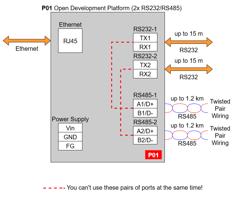
In the P01 gateway user should use only RS232 or only RS485 interface of one port as they occupy the same internal bus of the device. It means, don't use pairs: RS232-1 & RS485-1 at the same time and RS232-2 & RS485-2 at the same time!
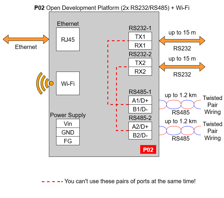
#### P02 - Open IoT and IIoT Gateway 2x RS232/RS485 + WiFi**®**
In the P02 gateway user should use only RS232 or only RS485 interface of one port as they occupy the same internal bus of the device. It means, don't use pairs: RS232-1 & RS485-1 at the same time and RS232-2 & RS485-2 at the same time!
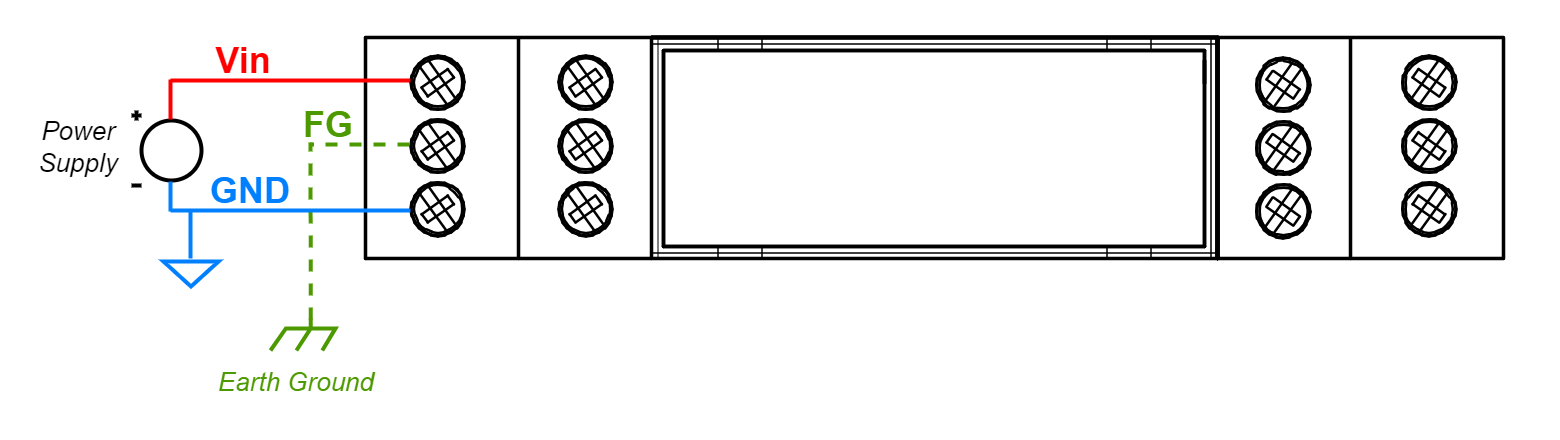
### Frame ground FG
Electronic circuits are constantly prone to electrostatic discharge ESD. Redisage Electronics modules feature a design for the frame ground terminal block FG. The frame ground provides a path for bypassing ESD, which provides enhanced static protection ESD abilities and ensures the module is more reliable. Connecting FG terminal block to the earth ground will bypass the ESD disturbances outside the device so will provide a better level of protection against ESD.
Frame Ground FG connection reference drawing is provided below.
If earth ground is not available FG can be left floating or it can be connected with the power supply GND.
### Pin assignments
| **P01**
[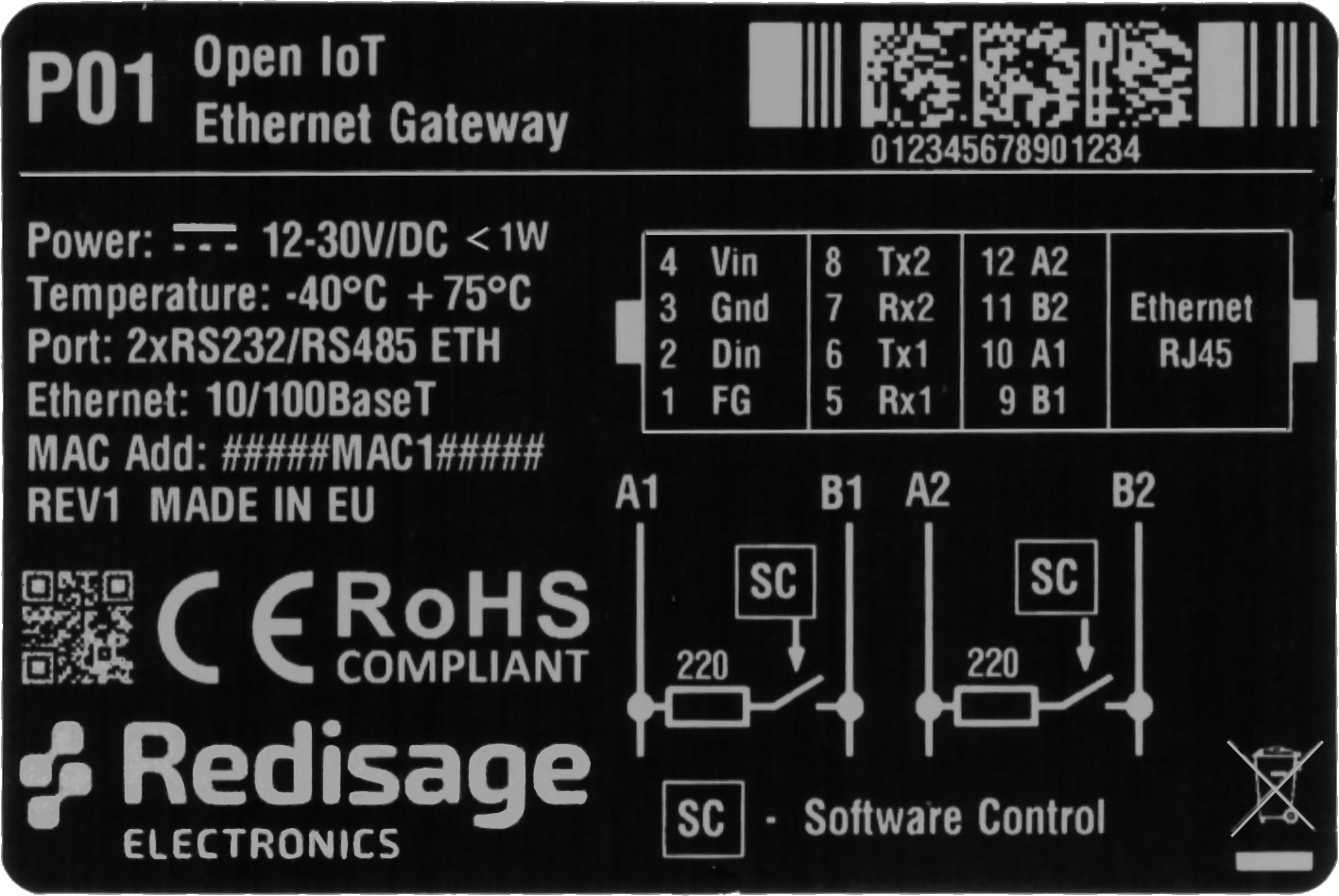](https://doc.redisage.com/uploads/images/gallery/2024-06/p01-name-plate-label-v1-1099.png)
| **P02**
[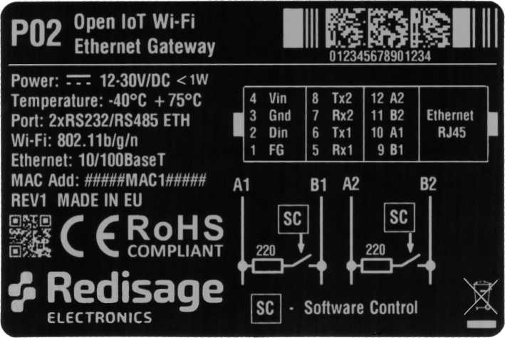](https://doc.redisage.com/uploads/images/gallery/2024-06/p02-name-plate-label-v1-1098.png)
|
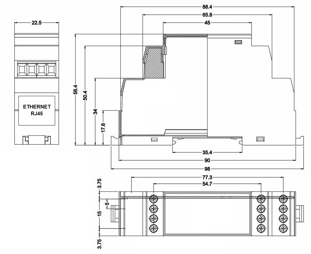
### Enclosure dimensions
2U Module Enclosure
98 x 22.5 x 56.4
Units: mm
[](https://doc.redisage.com/uploads/images/gallery/2024-05/AcYimage-3.webp)
### LED indicators
#### P01
- PW LED Blue - Power
- ETH LED Green - Network activity
- ST LED Red / Green / Blue - programmable LED
[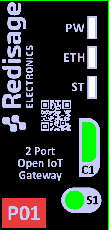](https://doc.redisage.com/uploads/images/gallery/2024-06/8kQimage.png)
#### P02
- PW LED Blue - Power
- ETH LED Green - Network activity
- ST LED Red / Green / Blue - programmable LED
[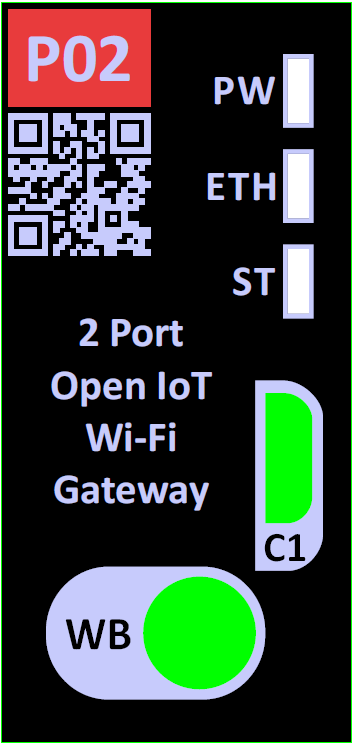](https://doc.redisage.com/uploads/images/gallery/2024-06/m6yimage.png)
### Additional notes
Wi-Fi® is a registered trademark of Wi-Fi Alliance®.
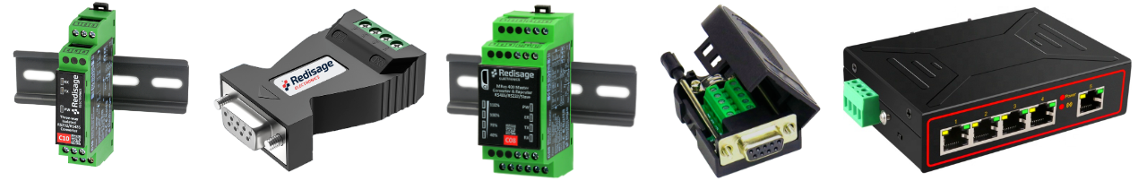
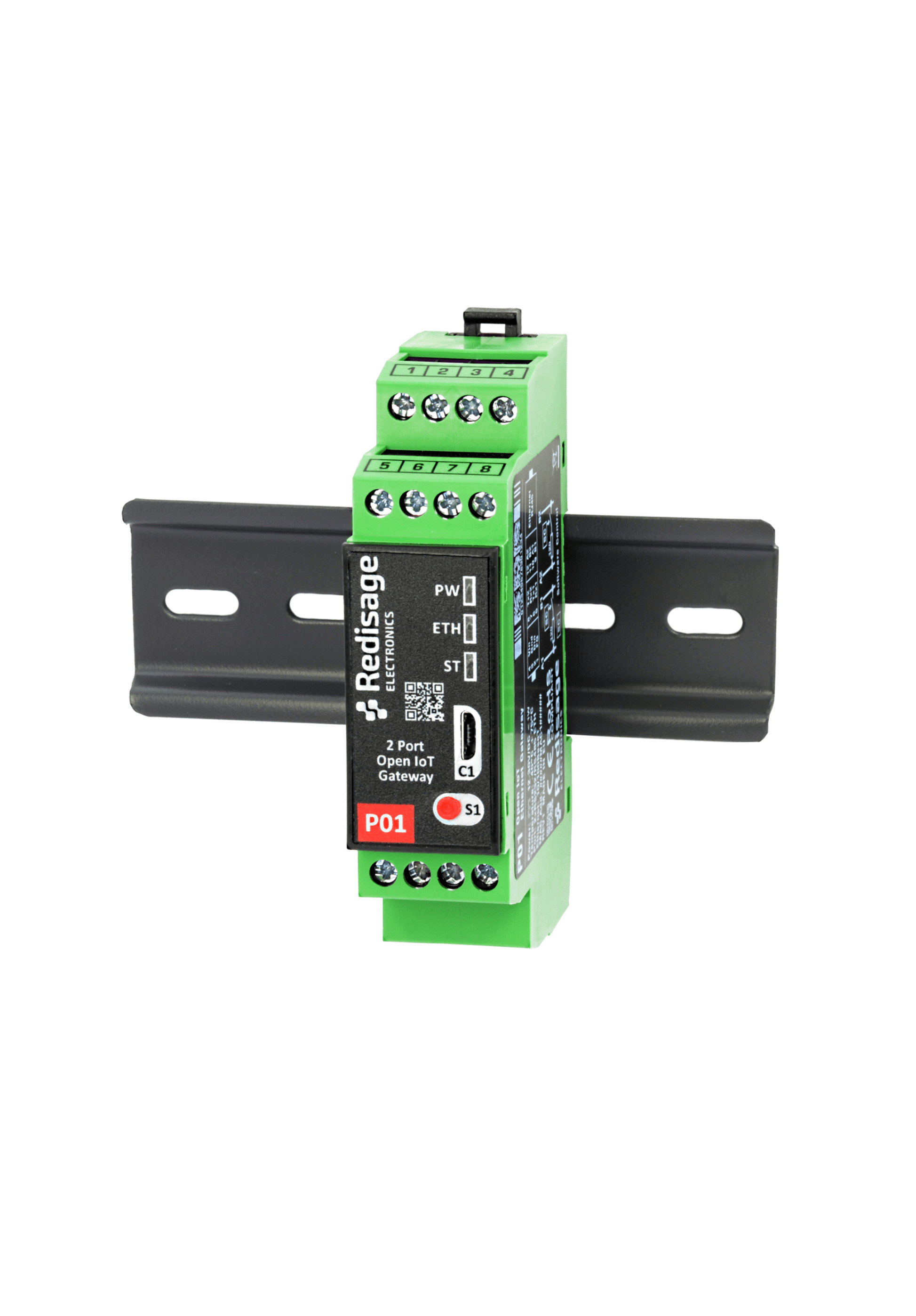
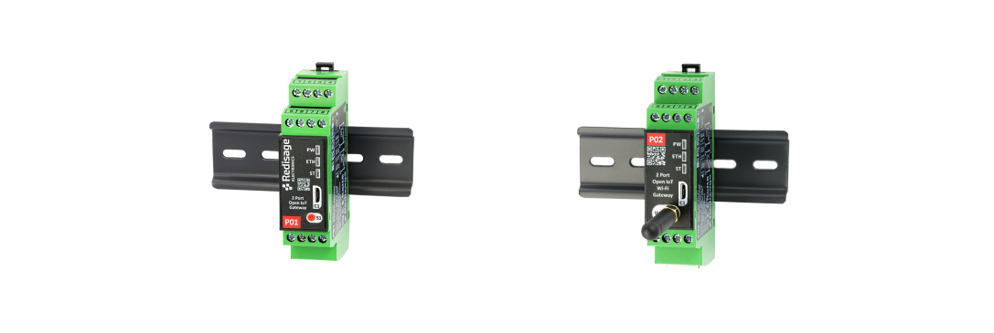
### Products family sample photo
[https://redisage.com](https://redisage.com/)
**DISCLAMER NOTES**
ALL PRODUCT, PRODUCT SPECIFICATIONS AND DATA ARE SUBJECT TO CHANGE WITHOUT NOTICE TO IMPROVE RELIABILITY, FUNCTION OR DESIGN OR OTHERWISE.
#### Datasheet-ID:
SR-D
# User Manual
# Introduction
{{@218}}
[](https://doc.redisage.com/uploads/images/gallery/2024-04/03721241-0db7-42b5-aad8-857a25a30481.png)
If you want to get started, make sure you have complete set of:
- [Tag-connect cable](https://redisage.com/en/products/p04-tc2050-idc-nl-10-pin-no-legs-cable-with-ribbon-connector-124)
- [Tag-connect retaining clip board](https://redisage.com/en/products/p05-tc2050-clip-3pack-retaining-clip-board-for-tc2050-nl-cables-3-pack-125) (optional)
- Open IoT and IIoT Gateway
- [USB Programmer](https://redisage.com/en/products/pac-iot/procesing-unit-cpu/esp32/p03-usb-programmer-for-esp32-p01-p02-open-gateways-ftdi-39.html)
[](https://doc.redisage.com/uploads/images/gallery/2024-04/c151dd12-f0ae-47d7-b01b-a1520c0afbba-1.png)
# New Page
# New Page
# New Page
# Hardware
## {{@218#bkmrk-open-iot-and-iiot-ga}}
### Features
| **Features**
| [](https://doc.redisage.com/uploads/images/gallery/2024-04/5e0098af-74b7-4f6a-84e2-63efb7875497-1.png) |
|---|
| Open IoT gateway
|
| ESD protection for the RS485 data line
|
| Power supply: +12 to +30 VDC
|
| Transmission speed up to 115200 bps
|
| Tx, Rx and power LED indicators
|
| RS485 embedded termination 120 ohm
|
| Optional W-iFi
|
| Operating temperatures: -40°C to +75°C
|
| DIN-rail mounting
|
| Dimensions: 90x56.4x22.5 mm
|
| **3 years warranty**
|
| **Customization of OEM is welcomed**
|
{{@169}}
### {{@190#bkmrk-specifications%E2%80%8E%E2%80%8E%E2%80%8E}}
{{@190#bkmrk-redisage-pn-p01-p02-}}
### LED indicators
| **Gateway P01**
| **Gateway P02**
|
| [](https://doc.redisage.com/uploads/images/gallery/2024-06/8kQimage.png) | [](https://doc.redisage.com/uploads/images/gallery/2024-06/m6yimage.png) |
| **LED indicator** | **Color** | **Function** | **LED indicator** | **Color** | **Function** |
| PW | Blue | Power | PW | Blue | Power |
| ETH | Green | Network activity | ETH | Green | Network activity |
| ST | Red / Green / Blue | Programmable LED | ST | Red / Green / Blue | Programmable LED |
### {{@190#bkmrk-pin-assignments}}
{{@190#bkmrk-p01-%C2%A0-p02-%C2%A0}}
### Board overview
[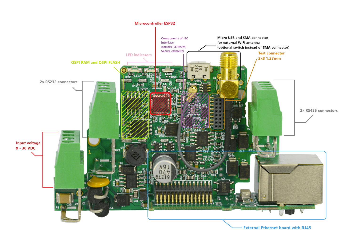](https://doc.redisage.com/uploads/images/gallery/2025-10/image.png)
The complete Open IoT and IIoT Gateway kit consists of:
- developer module
- RJ45 network adapter
- hardware programmer
[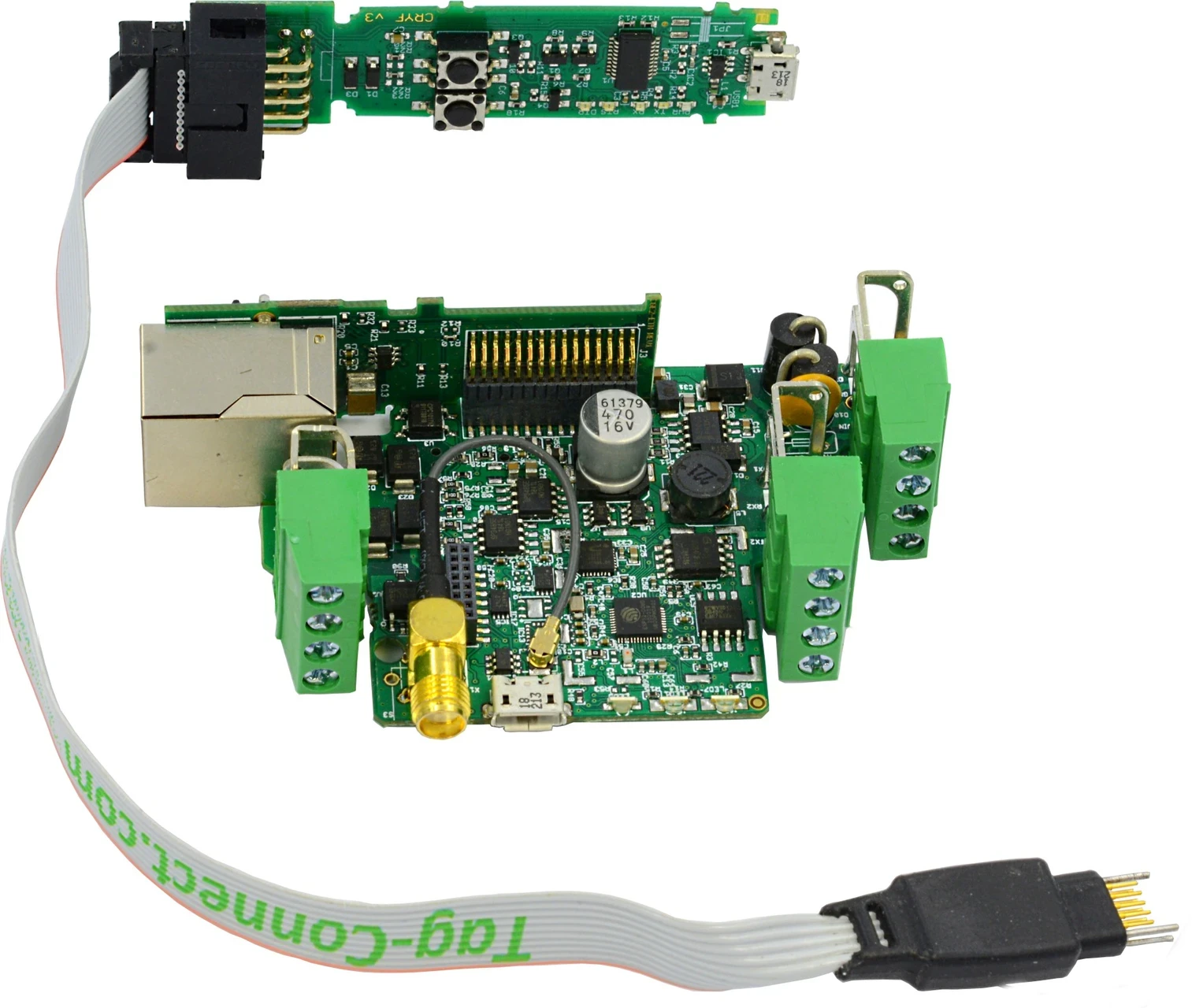](https://doc.redisage.com/uploads/images/gallery/2024-06/image-4.webp)
#### Power input pinout
[](https://doc.redisage.com/uploads/images/gallery/2024-06/ijLimage.png)
- **VCC** - power supply input 9-30 VDC
- **GND** - power supply ground
- **DI** - digital input (used while there is no button mounted and it can be shorten only to GND)
- **FG** - frame ground
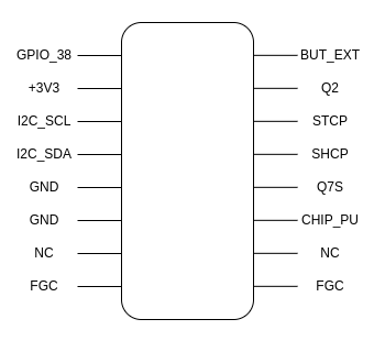
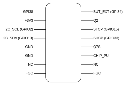
#### Test connectors
Provided test connectors can be used for board debugging.
- **GPIO\_38** - ESP32 general purpose input
- **3V3** - 3.3 VDC
- **I2C\_SCL,** **I2C\_SDA** - I2C connectors
- **GND** - ground
- **NC** - not connected
- **FGC** - frame ground connector
- **BUT\_EXT** - button test line (default: high state)
- **Q2** - Q2 output of parallel register (74HC595BQ)
- **STCP** - clock input of serial register (74HC595BQ)
- **SHCP** - clock input of buffer register (74HC595BQ)
- **Q7S** - output of serial register (74HC595BQ)
- **CHIP\_PU** - chip power up line ('1' - powers chip up)
#### Button / antenna
The antenna connector can be replaced with a button which can be used for, for example, restoring device to the default configuration, saved in EEPROM.
[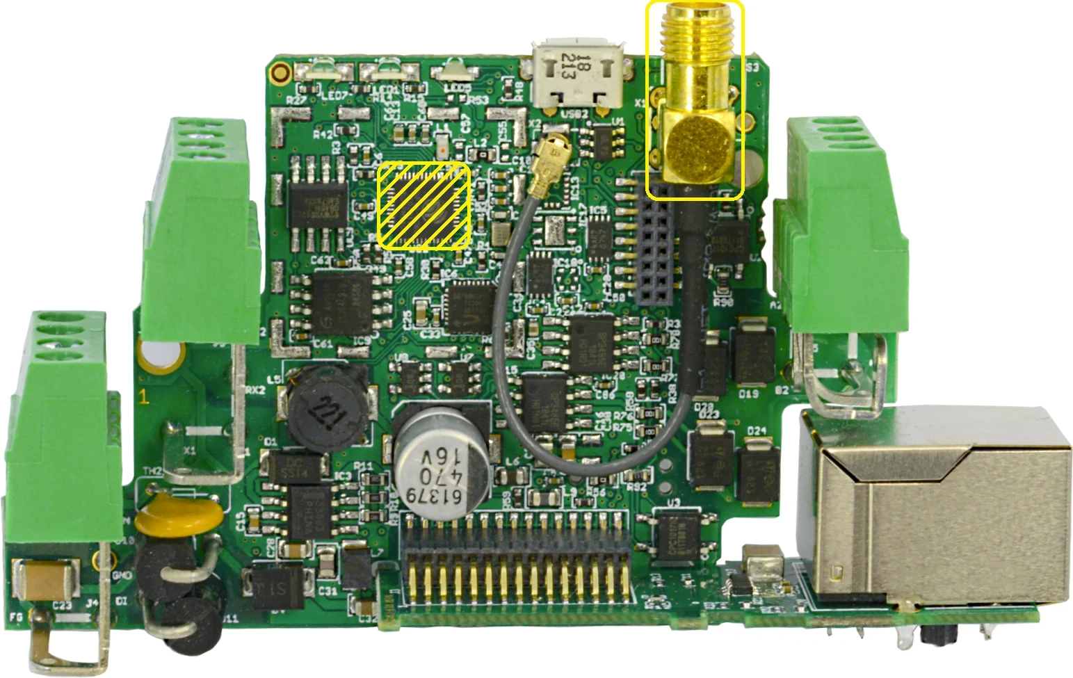](https://doc.redisage.com/uploads/images/gallery/2024-06/image-30.webp)
In order to use the button instead of the antenna, the R52 resistor (near the microUSB connector, on the bottom side) has to be soldered to the board.
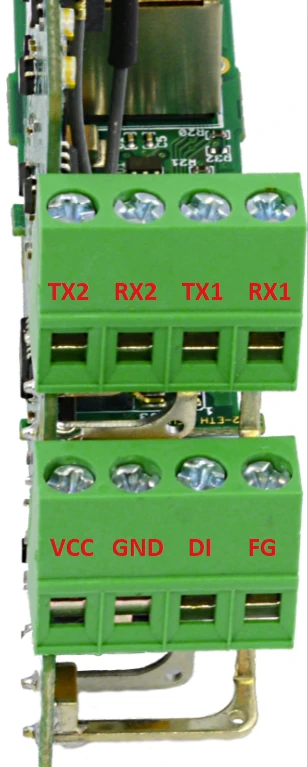
#### RS232 ports
The device has 2 independent RS485 ports.
[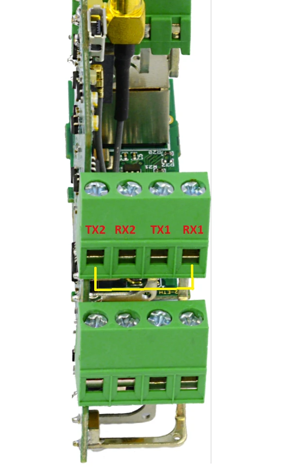](https://doc.redisage.com/uploads/images/gallery/2024-06/1qnimage.png)
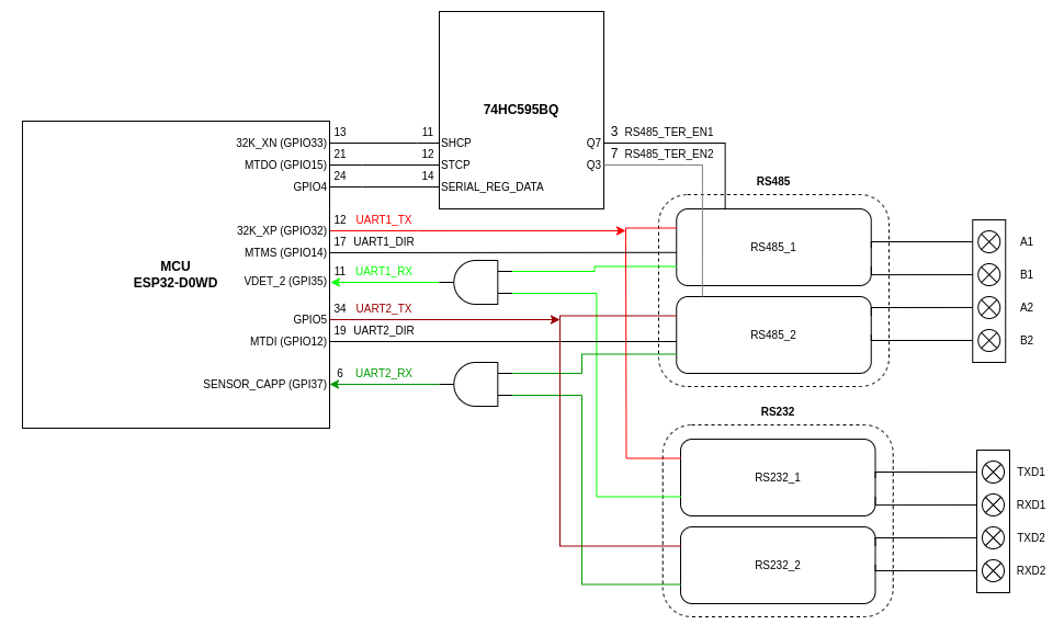
#### RS485 ports
The device is equipped with two MAX481 transceivers that enable communication in the RS485 standard on two channels independently.
[](https://doc.redisage.com/uploads/images/gallery/2024-06/Ei3image.png)
As the RS485\_1 / RS232\_1 and RS485\_2 / RS232\_2 standards use common microcontroller serial ports, it is possible to use only 1 interface from the pair at a time.
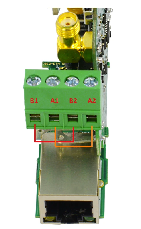
#### ETHERNET
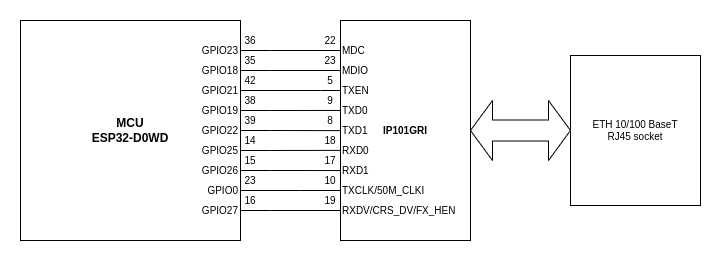
In order to support the Ethernet network interface communication, the network adapter available in the kit must be installed on the module (pay attention to its correct installation). This interface is supported by the external IP101G physical layer which communicates with the ESP32 microcontroller.
[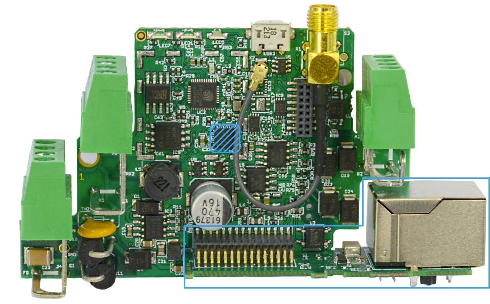](https://doc.redisage.com/uploads/images/gallery/2024-06/image-33.webp)
####
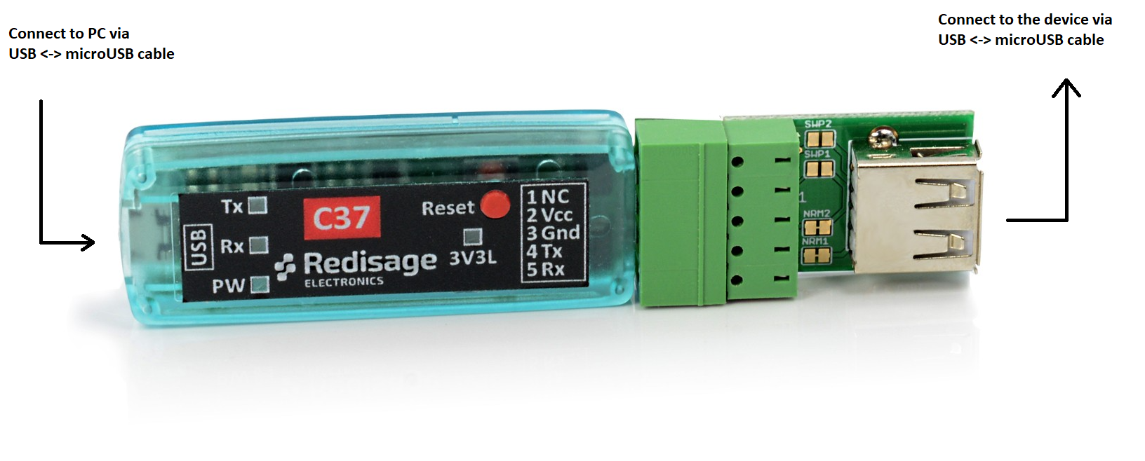
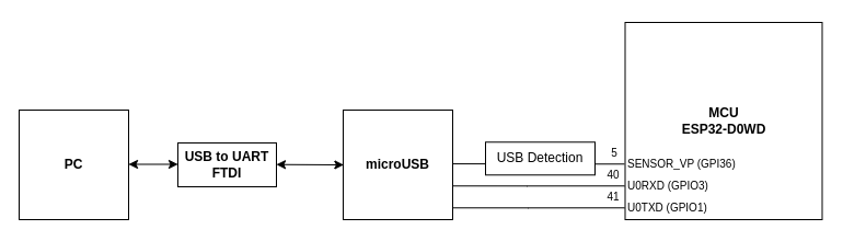
#### Micro USB Connector
You need the [C37](https://doc.redisage.com/books/usb-rs232-rs485-converters/page/usb-ftdi-converters-data-sheet) USB to UART FTDI Converter to connect the device with a PC console via USB.
[](https://doc.redisage.com/uploads/images/gallery/2025-10/Yf5image.png)
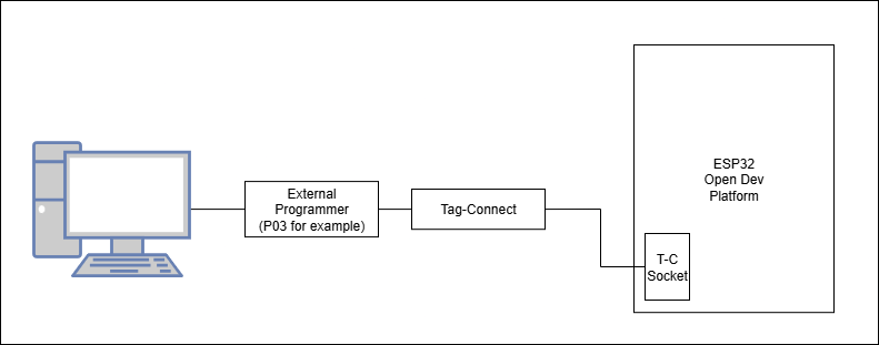
### Programming
The device can be programmed only with the external hardware programmer (for example [P03](https://doc.redisage.com/books/usb-rs232-rs485-converters/page/usb-ftdi-esp32-programmer-data-sheet)) connected via Tag-Connect connector ([P04](https://redisage.com/en/products/p04-tc2050-idc-nl-10-pin-no-legs-cable-with-ribbon-connector-124)).
[](https://doc.redisage.com/uploads/images/gallery/2024-06/image-6.webp)
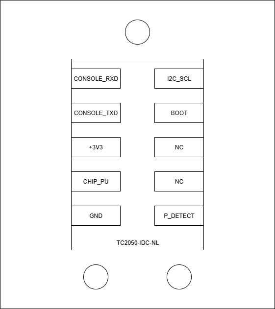
#### Tag-Connect Socket pinout
[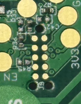](https://doc.redisage.com/uploads/images/gallery/2025-10/PShimage.png)
# Programming
## {{@218#bkmrk-open-iot-and-iiot-ga}}
### Install IDE
Please, follow the instructions located [here](https://docs.espressif.com/projects/esp-idf/en/latest/esp32/get-started/index.html) to install the ESP-IDF framework on your local machine. ESP-IDF is available both on [Windows](https://docs.espressif.com/projects/esp-idf/en/latest/esp32/get-started/windows-setup.html) and [Linux](https://docs.espressif.com/projects/esp-idf/en/latest/esp32/get-started/linux-macos-setup.html). It can also be installed through some popular IDEs: [VS Code](https://docs.espressif.com/projects/vscode-esp-idf-extension/en/latest/) or [Eclipse](https://github.com/espressif/idf-eclipse-plugin/blob/master/README.md).
ESP-IDF is required to build the examples written in C for the device. However, it can also be programmed in [MicroPython](https://docs.micropython.org/en/latest/esp32/tutorial/intro.html) ([Thonny](https://thonny.org/)).
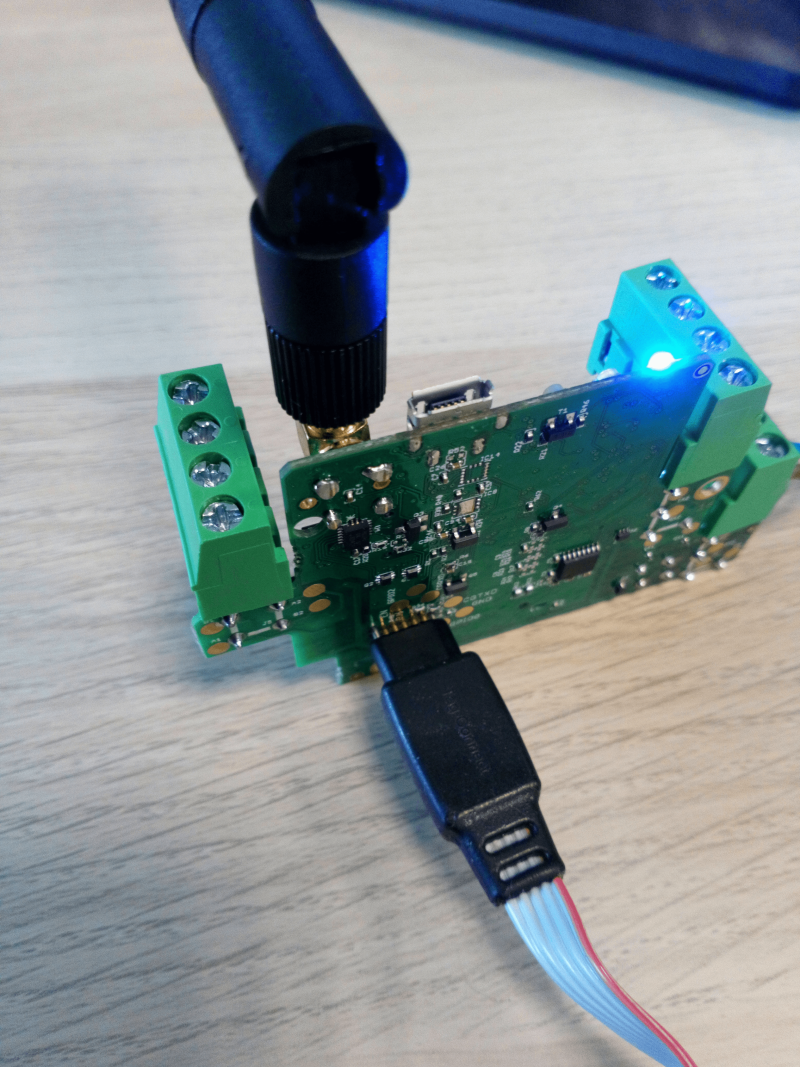
### Connect the programmer
ESP32 IoT and IIoT Gateways can be programmed only with the external hardware programmer (for example [**P03**](https://doc.redisage.com/link/219#bkmrk-page-title)) connected via the Tag-Connect connector. After connecting it to the board and a PC, a new COM port should be available.
| [](https://doc.redisage.com/uploads/images/gallery/2024-06/image-4.webp) | [](https://doc.redisage.com/uploads/images/gallery/2024-06/image-6.webp) |
#### Tag-Connect Socket pinout
[](https://doc.redisage.com/uploads/images/gallery/2025-10/PShimage.png)
###
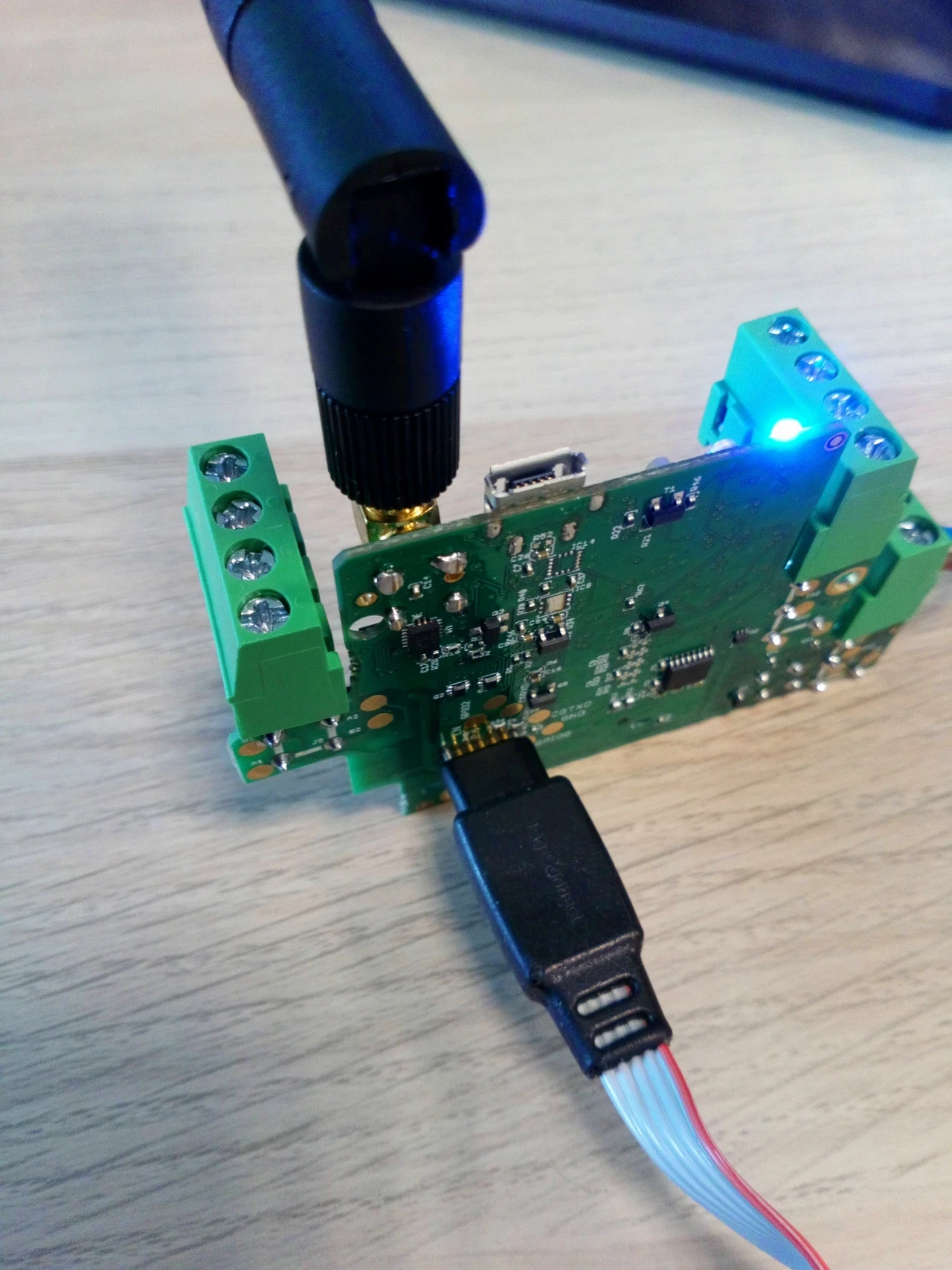
### Connect the power supply
In order to successfully flash the device, it has to be connected to the power supply (9 - 30 VDC) using the VCC and GND connectors.
[](https://doc.redisage.com/uploads/images/gallery/2024-06/EkQimage.png)
### Create your own programs
After all of the above steps are done, the device should be ready to be programmed. Example scripts and repositories are available [here](https://doc.redisage.com/books/esp32-open-iot-and-iiot-gateways/chapter/examples).
### Build, flash and monitor the device
#### VS Code ESP-IDF extension
1. Make sure that there is a ".vscode" folder in the project tree. If not, add it with the "F1" + "ESP-IDF: Add vscode Configuration Folder" command.
[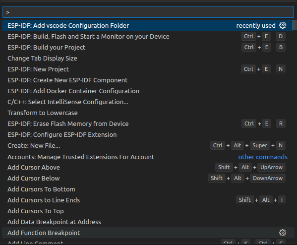](https://doc.redisage.com/uploads/images/gallery/2024-06/Rpfimage.png)
2. Set your device target with "F1" + "ESP-IDF: Set Espressif Device Target". Then choose current workspace folder and then "esp32". Lastly choose "Custom board" and confirm it.
[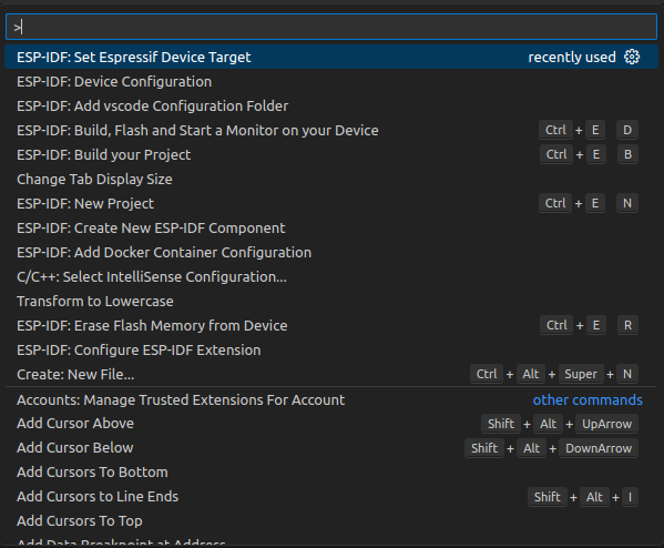](https://doc.redisage.com/uploads/images/gallery/2024-06/GX6image.png)
[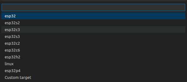](https://doc.redisage.com/uploads/images/gallery/2024-06/ucEimage.png)
[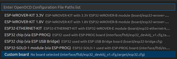](https://doc.redisage.com/uploads/images/gallery/2024-06/RY3image.png)
3. Set port where the device is attached to with "F1" + "ESP-IDF: Select Port to Use (COM, tty, usbserial)".
[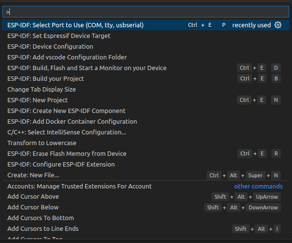](https://doc.redisage.com/uploads/images/gallery/2024-06/Qkkimage.png)
4. Finally select "UART" flash method with "F1" + "ESP-IDF: Select Flash Method".
[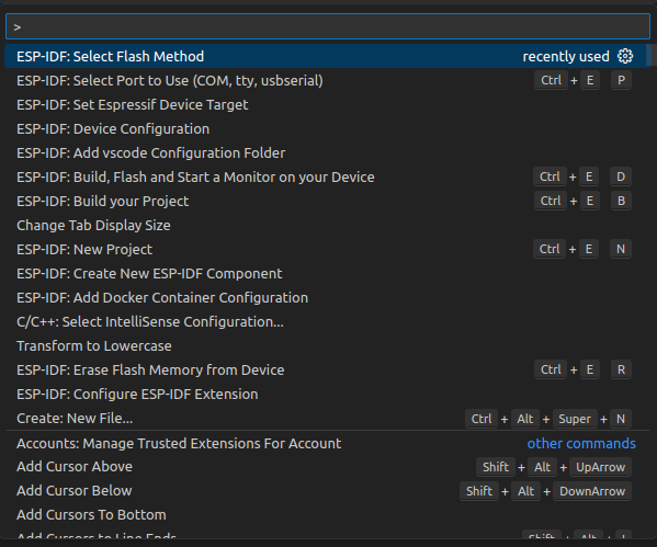](https://doc.redisage.com/uploads/images/gallery/2024-06/Aa9image.png)
[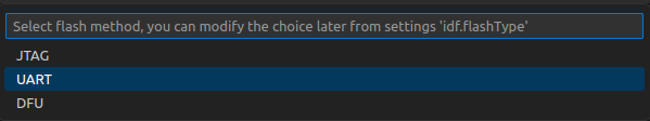](https://doc.redisage.com/uploads/images/gallery/2024-06/3PAimage.png)
5. Build your project, flash it to the device and open a serial monitor with the "F1" + "ESP-IDF: Build, Flash and Start a Monitor on your Device". If everything was set properly the serial monitor should open after a successful flash.
[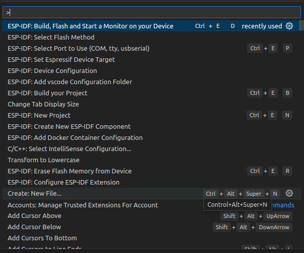](https://doc.redisage.com/uploads/images/gallery/2024-06/PjNimage.png)
#### Thonny
1. Hit "F5" button in Thonny IDE to run the current script.
[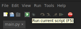](https://doc.redisage.com/uploads/images/gallery/2024-06/Q0Kimage.png)
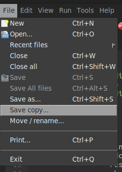
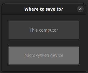
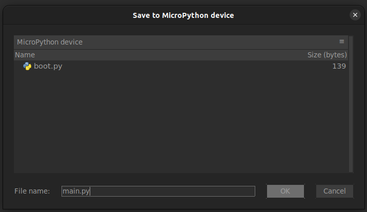
2. Click "File" -> "Save copy..." -> "MicroPython device" and save this file as "main.py" in order to execute this code every time the gateway powers on.
[](https://doc.redisage.com/uploads/images/gallery/2024-06/9OGimage.png)
[](https://doc.redisage.com/uploads/images/gallery/2024-06/y5yimage.png)
[](https://doc.redisage.com/uploads/images/gallery/2024-06/Wn4image.png)
# Other IDEs
## {{@218#bkmrk-open-iot-and-iiot-ga}}
The device can be programmed also in other development environments. Programming gateways is supported on every popular operating systems like Windows, Linux or MAC OS. This document was prepared in reference to Windows.
### ESP-IDF framework
The main tool is ESP-IDF framework provided by Espressif. To get more information about installation, visit manufacturer’s
website: [Get Started - ESP32 - — ESP-IDF Programming Guide latest documentation](https://docs.espressif.com/projects/esp-idf/en/latest/esp32/get-started/).
Manual Installation of ESP-IDF: [Standard Setup of Toolchain for Windows - ESP32 - — ESP-IDF Programming Guide latest documentation](https://docs.espressif.com/projects/esp-idf/en/latest/esp32/get-started/windows-setup.html).
During the ESP-IDF installation you might be asked for install Eclipse additionally.
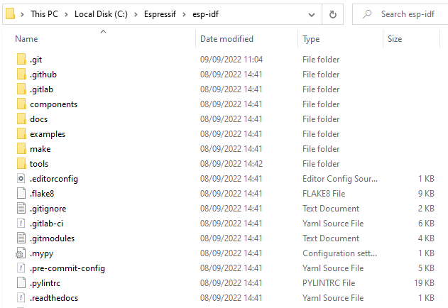
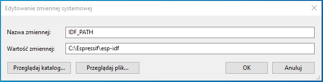
After successful process it is necessary to add new enviroment variables.
Variables names:
- IDF\_PATH - paste the path of the directory with ESP-IDF framework
- IDF\_TOOLS\_PATH - paste the path of the directory with ESP-IDF tools
[](https://doc.redisage.com/uploads/images/gallery/2024-04/f8899686-b97f-47ad-9a49-32b7a88b725c.png)
[](https://doc.redisage.com/uploads/images/gallery/2024-04/11e4e082-6da0-4bff-9e2b-33098e5062b4.png)
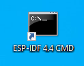
Finally you can run ESP-IDF CMD and start to manage your project. There should be an icon on the desktop or easy access to ESP-IDF.
[](https://doc.redisage.com/uploads/images/gallery/2024-04/e4d424cb-4a06-45e7-9c6b-3160777c93fe.png)
##### Create new project
idf.py create-project -p <name>
##### Build project
idf.py -p <port> build
##### Flash project
idf.py -p <port> flash
idf.py -p <port> flash monitor
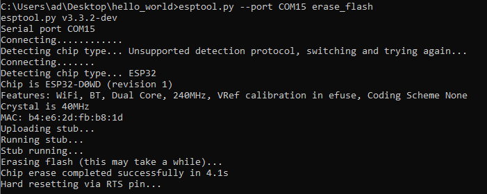
##### Erase flash
esptool.py --port <port> erase\_flash
### MinGW
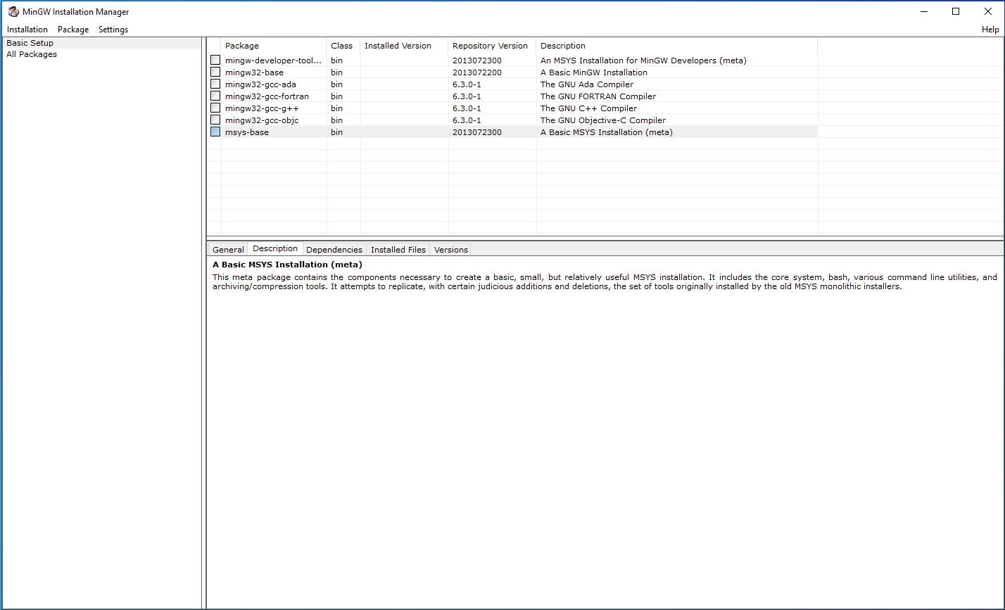
Download MinGW with GUI from MinGW - Minimalist GNU for Windows and install on your PC. After a successful installation run MinGW Installation Manager (GUI).
[](https://doc.redisage.com/uploads/images/gallery/2024-04/04cab29c-1dae-42b6-a0c6-d013d37ffadd.png)
Now we need to install Basic Setup. Right click on every square fields in “Package” tab, then “Mark for Installation”. Next, in “Installation” tab click on “Apply Changes” and then “Apply”.
| [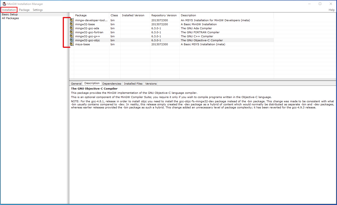](https://doc.redisage.com/uploads/images/gallery/2024-04/67a06d6c-6dc6-4b4d-a4c4-25afbe706867.png) | [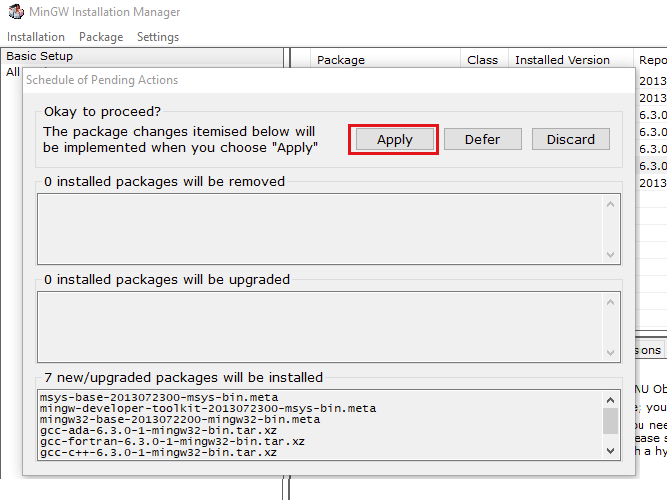](https://doc.redisage.com/uploads/images/gallery/2024-04/5e24edfe-6c42-48ba-bfb8-7701b7b71c77.png) |
To check if the installation is successful, open Command line and type:
```bash
gcc --version
```
[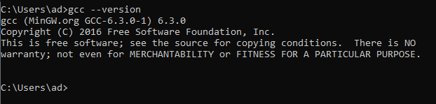](https://doc.redisage.com/uploads/images/gallery/2024-04/d9abc443-bde5-4a2d-b6c4-55c0820cbe99.png)
### IDE
You can edit code in your preferred IDE as ESP-IDF is handling the final build and flash.
Recommanded IDEs:
- [CodeBlocks](https://www.codeblocks.org/downloads/)
- [Visual Studio Code](https://code.visualstudio.com/download)
- [Eclipse](https://www.eclipse.org/downloads/)
- [Thonny IDE](https://thonny.org/)
#### Visual Studio Code
- Download the package with example projects for IoT Gateway.
- Select one of the demos and copy it to a new directory.
- Open Visual Studio Code and click on the extension tab.
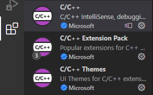
- Install and configure C/C++ extensions.
[](https://doc.redisage.com/uploads/images/gallery/2024-04/1dbaaf87-a363-40c9-a7e7-0ac416be86bd.png)
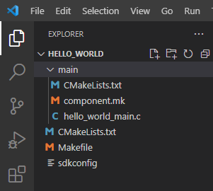
- Open directory in VS Code.
[](https://doc.redisage.com/uploads/images/gallery/2024-04/7bfa65be-c841-4617-a3e5-b5c0a473d15d.png)
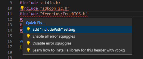
- If errors occur, edit “includePath” settings.
[](https://doc.redisage.com/uploads/images/gallery/2024-04/5aa5ab7d-6595-47e4-bdd4-f9b552cbee39.png)
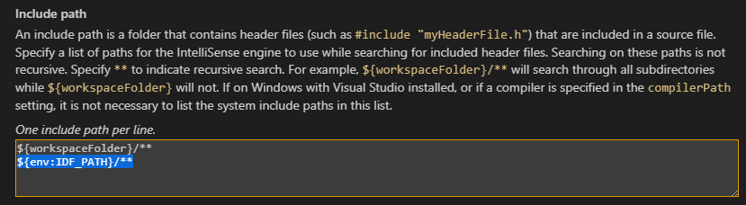
- Add the line "${env:IDF\_PATH}/\*\*".
[](https://doc.redisage.com/uploads/images/gallery/2024-04/c3529dd3-920f-44dd-beb6-9629385e9aaf.png)
- Now code is ready to be modified.
- To build or flash project, use ESP-IDF CMD.
Visual Studio Code provides an extension “Espressif IDF” which has some issues at this moment. However it is not essential for editing code.
#### CodeBlocks
- Download the package with example projects for IoT Gateway.
- Select one of the demos and copy it to a new directory.
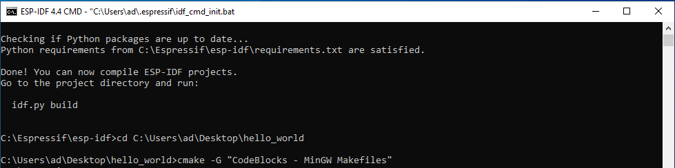
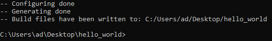
- Run ESP-IDF CMD, set the path to your project and then generate project for CodeBlocks:
```bash
cmake -G "CodeBlocks - MinGW Makefiles"
```
[](https://doc.redisage.com/uploads/images/gallery/2024-04/1ccc0952-02b0-414f-93ee-aae2e4ce9fd7.png)
[](https://doc.redisage.com/uploads/images/gallery/2024-04/0b03cd5a-5116-422e-a5de-c47d6e7a569b.png)
- Run CodeBlocks. Click on "File → Open…", find .cbp type file and click on “Open”.
[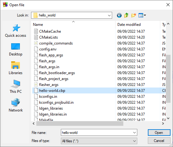](https://doc.redisage.com/uploads/images/gallery/2024-04/7d20079f-f797-4a2d-9d74-4eb40a308cb3.png)
- After this, there should be a project tree available and code is ready to be modified.
[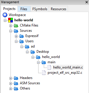](https://doc.redisage.com/uploads/images/gallery/2024-04/06b76408-0f58-47f0-8894-a3e115cf8562.png)
- To build or flash project, use ESP-IDF CMD.
#### Thonny IDE
- Download and install Python interpreter.
- Download the package with example projects for IoT Gateway.
- Select one of the demos and copy it to a new directory.
- Run ESP-IDF CMD, erase flash using:
```bash
esptool.py --port erase_flash
```
[](https://doc.redisage.com/uploads/images/gallery/2024-04/5af1e224-2094-49a3-96c6-80545ce5d8f5.png)
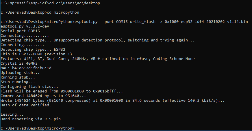
- Download [firmware ](https://micropython.org/download/ESP32_GENERIC/)which allows to run microPython.
- Flash .bin file using:
```bash
esptool.py --port write_flash -z 0x1000
```
[](https://doc.redisage.com/uploads/images/gallery/2024-04/2aae30b3-126b-420b-ad12-a8244c9384de.png)
- Open serial port monitor like “Putty”, set COM port, baudrate, connection type to serial and click on “Open”.
[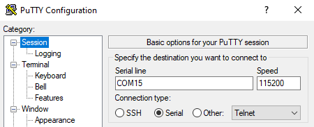](https://doc.redisage.com/uploads/images/gallery/2024-04/e6a97031-3316-44aa-b31a-8259727b87d8.png)
- Now you can run Python console on ESP32.
[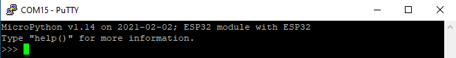](https://doc.redisage.com/uploads/images/gallery/2024-04/2ba64294-f54b-4a64-a837-dae5c60e23d9.png)
- Download and install [Thonny IDE](https://thonny.org/).
- Click on "Tools → Options → Interpreter". In this tab you can choose an interpreter and COM port.
[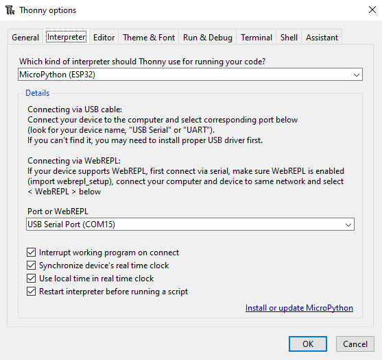](https://doc.redisage.com/uploads/images/gallery/2024-04/57f3a021-1371-45d6-b13f-c21b10f9d21c.png)
- After all the process Thonny IDE is ready to work.
[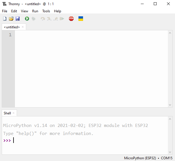](https://doc.redisage.com/uploads/images/gallery/2024-04/f70a61dc-1ec9-4ea3-9960-e90cfd98c478.png)
- To flash the demo, open file in Thonny IDE. Next click on green button to run the current script.
### Uploading firmware
To upload firmware, you need to use external programmer with Tag-connect.
[](https://doc.redisage.com/uploads/images/gallery/2024-04/3665aeb3-48ae-44d7-9f2d-4d2decaefb59-1.png)
# Pin Map
## {{@218#bkmrk-open-iot-and-iiot-ga}}
### CGE2 rev. 4.1
| **Element** | **Connection** |
| **LED**
|
| Power LED7 (blue) | +3V3 |
| ETHERNET LED1 (green) | ETH\_LED3/PHY\_AD3 |
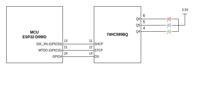
| RGB programmable LED5 (red) | Q6 |
| RGB programmable LED5 (blue) | Q5 |
| RGB programmable LED5 (green) | Q4 |
| **74HC595BQ shift register** |
| VCC | +3V3 |
| Q7S | Q7S |
| Q0 | Q0 |
| Q1 | Q1 |
| Q2 | Q2 |
| Q3 | RS485\_TER\_EN2 |
| Q4 | Q4 |
| Q5 | Q5 |
| Q6 | Q6 |
| Q7 | RS485\_TER\_EN1 |
| MR/ | CHIP\_PU (pull up) |
| OE/ | GND |
| DS | SERIAL\_REG\_DATA |
| SHCP | SHCP |
| STCP | STCP (pull down) |
| GND | GND |
| TPAD | GND |
| **MAX481CSA\_1 UART RS485 transceiver** |
| DI | UART1\_TX |
| DE | UART1\_DIR |
| RE/ | UART1\_DIR |
| RO | UART1\_RX |
| A | A\_1 |
| B | B\_1 |
| **MAX481CSA\_2 UART RS485 transceivers** |
| DI | UART2\_TX |
| DE | UART2\_DIR |
| RE/ | UART2\_DIR |
| RO | UART2\_RX |
| A | A\_2 |
| B | B\_2 |
| **ST3232BTR RS232 driver and receiver** |
| C1+ | C1 (100 nF) |
| C1- | C1 (100 nF) |
| C2+ | C2 (100 nF) |
| C2- | C2 (100 nF) |
| T1IN | UART1\_TX
|
| T2IN | UART2\_TX
|
| R1OUT | UART1\_RX
|
| R2OUT | UART2\_RX
|
| V+ | C3 (100 nF)
|
| V- | C4 (100 nF)
|
| T1OUT | TXD1
|
| T2OUT | TXD2
|
| R1IN | RXD1
|
| R2IN | RXD2
|
| **USBLC6-2SC6 ESD protection**
|
| VCC | USB\_V
|
| GND | GND
|
| IO1\_A | DATA-
|
| IO1\_B | CONSOLE\_RX
|
| IO2\_A | DATA+
|
| IO2\_B | CONSOLE\_TX
|
| **MicroUSB type B**
|
| V\_BUS | USB\_V
|
| D- | DATA- (CONSOLE\_RX)
|
| D+ | DATA+ (CONSOLE\_TX)
|
| ID | GND
|
| GND | GND
|
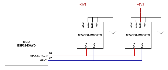
| **M24C02-RMC6TG\_1 I2C EEPROM**
|
| E0 | GND
|
| E1 | GND
|
| E2 | +3V3
|
| VSS | GND
|
| VCC | +3V3
|
| WC/ | GND
|
| SCL | I2C\_SCL
|
| SDA | I2C\_SDA
|
| **M24C02-RMC6TG\_2 I2C EEPROM**
|
| E0 | +3V3
|
| E1 | +3V3
|
| E2 | GND
|
| VSS | GND
|
| VCC | +3V3
|
| WC/ | GND
|
| SCL | I2C\_SCL (pull up)
|
| SDA | I2C\_SDA (pull up)
|
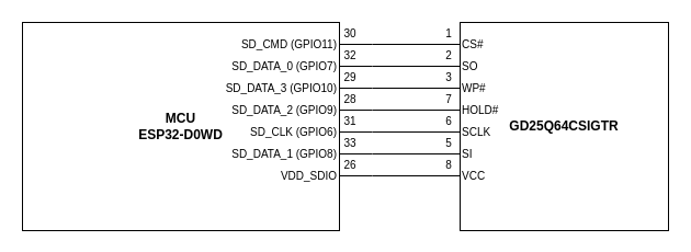
| **GD25Q64CSIGTR QSPI FLASH**
|
| CS# | SPICS0
|
| SO | SPIQ
|
| WP# | SPIWP
|
| VSS | GND
|
| VCC | VDD\_SDIO
|
| HOLD# | SPIHD
|
| SCLK | SPICLK
|
| SI | SPID
|
| **IP101GRI ETHERNET transceivers**
|
| MDC | ETH\_MDC
|
| MDIO | ETH\_MDIO
|
| MDI\_TP | TXD+
|
| MDI\_TN | TXD-
|
| MDI\_RP | RXD+
|
| MDI\_RN | RXD-
|
| X2 | - |
| X1 | GND |
| RESET\_N | ETH\_RESET\_N (pull up) |
| ISET | ETH\_ISET (pull down) |
| LED0/PHY\_AD0 | ETH\_LED0/PHY\_AD0 (pull up) |
| LED3/PHY\_AD3 | ETH\_LED3/PHY\_AD3 (pull down) |
| TEST\_ON | - |
| REGOUT | C21 (100 nF), C35 (10 uF) |
| VDDIO | +3V3 |
| AVDD33 | +3V3 |
| GND | GND |
| TXEN | ETH\_TX\_EN |
| TXER/FXSD | - |
| TXCLK/50M\_CLKI | ETH\_CLK\_IN |
| TXD0 | ETH\_TXD0 |
| TXD1 | ETH\_TXD1 |
| TXD2 | - |
| TXD3 | - |
| RXDV/CRS\_DV/FX\_HEN | ETH\_RX\_CRS\_DV |
| RXCLK/50M\_CLKO | - |
| RXD0 | ETH\_RXD0 |
| RXD1 | ETH\_RXD1 |
| RXD2 | - |
| RXD3 | - |
| RXER/INTR\_32 | - |
| COL/RMII | ETH\_COL/RMII (pull up) |
| CRS/LEDMOD | - |
| **ESP32-DOWD** |
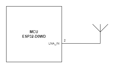
| VDDA\_1 | +3V3 |
| LNA\_IN | ANT |
| VDD3P3\_1 | VDD3P3 (+3V3) |
| VDD3P3\_2 | VDD3P3 (+3V3) |
| SENSOR\_VP (GPI36) | USB\_DETECT (pull down) |
| SENSOR\_CAPP (GPI37) | UART2\_RX |
| SENSOR\_CAPN (GPI38) | GPI\_38 |
| SENSOR\_VN (GPI39) | P\_DETECT (pull up) |
| CHIP\_PU | CHIP\_PU (pull up) |
| VDET\_1 (GPI34) | BUTTON\_IN (pull up) |
| VDET\_2 (GPI35) | UART1\_RX |
| 32K\_XP (GPIO32) | UART1\_TX |
| 32K\_XN (GPIO33) | SHCP |
| GPIO25 | ETH\_RXD0 |
| GPIO26 | ETH\_RXD1 |
| GPIO27 | ETH\_RX\_CRS\_DV |
| MTMS (GPIO14) | UART1\_DIR |
| MTDI (GPIO12) | UART2\_DIR |
| VDD3P3\_RTC | +3V3 |
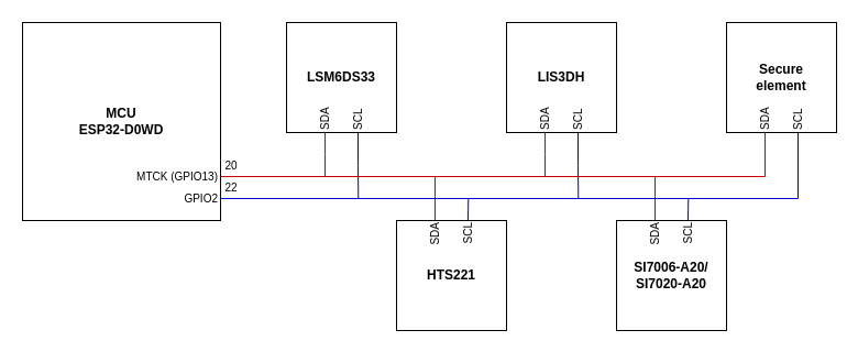
| MTCK (GPIO13) | I2C\_SDA (pull up) |
| MTDO (GPIO15) | STCP (pull down)
|
| GPIO2 | I2C\_SCL (pull up) |
| GPIO0 | ETH\_CLK\_IN, SPICS1 |
| GPIO4 | SERIAL\_REG\_DATA |
| GPIO16 | ETH\_CLK |
| VDD\_SDIO | VDD\_SDIO |
| GPIO17 | SPICS1 |
| SD\_DATA\_2 (GPIO9) | SPIHD |
| SD\_DATA\_3 (GPIO10) | SPIWP |
| SD\_CMD (GPIO11) | SPICS0 |
| SD\_CLK (GPIO6) | SPICLK |
| SD\_DATA\_0 (GPIO7) | SPIQ |
| SD\_DATA\_1 (GPIO8) | SPID |
| GPIO5 | UART2\_TX |
| GPIO18 | ETH\_MDIO |
| GPIO23 | ETH\_MDC
|
| VDD3P3\_CPU | +3V3 |
| GPIO19 | ETH\_TXD0 |
| GPIO22 | ETH\_TXD1 |
| U0RXD (GPIO3) | CONSOLE\_RX |
| U0TXD (GPIO1) | CONSOLE\_TX |
| GPIO21 | ETH\_TX\_EN |
| VDDA\_2 | +3V3 |
| XTAL\_N | XTAL\_N |
| XTAL\_P | XTAL\_P |
| VDDA\_3 | +3V3 |
| CAP2 | CAP2 |
| CAP1 | CAP1 |
| GND | GND |
### Optional
| **Element** | **Connection** |
| **Expander** |
| 1 | FGC |
| 2 | - |
| 3 | CHIP\_PU (pull up) |
| 4 | Q7S |
| 5 | SHCP |
| 6 | STCP (pull down) |
| 7 | Q2 |
| 8 | BUT\_EXT |
| 9 | GPI\_38 |
| 10 | +3V3 |
| 11 | I2C\_SCL (pull up) |
| 12 | I2C\_SDA (pull up) |
| 13 | GND |
| 14 | GND |
| 15 | - |
| 16 | FGC |
| **Programmer**
|
| 1 | CONSOLE\_RX |
| 2 | CONSOLE\_TX |
| 3 | +3V3 |
| 4 | CHIP\_PU |
| 5 | GND |
| 6 | P\_DETECT |
| 7 | - |
| 8 | - |
| 9 | BOOT |
| 10 | I2C\_SCL |
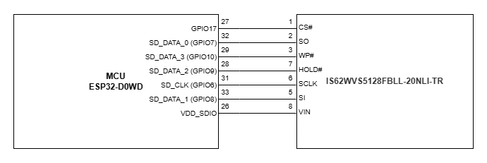
| **870-62WS5128 QSPI RAM**
|
| CS# | SPICS1
|
| SO | SPIQ
|
| WP# | SPIWP
|
| VSS | GND
|
| VCC | VDD\_SDIO
|
| HOLD# | SPIHD
|
| SCLK | SPICLK
|
| SI | SPID
|
| **Secure element**
|
| SCL | I2C\_SCL (pull up)
|
| SDA | I2C\_SDA (pull up)
|
| VCC | +3V3
|
| IO | -
|
| GND | GND
|
| **SI7006-A20/SI7020-A20 humidity and temperature sensor**
|
| SDA | I2C\_SDA (pull up)
|
| GND | GND
|
| DNC1 | -
|
| SCL | I2C\_SCL (pull up)
|
| VDD | +3V3
|
| DNC2 | -
|
| **HTS221 humidity and temperature sensor**
|
| VDD | +3V3
|
| CS | +3V3
|
| GND | GND
|
| SCL/SPC | I2C\_SCL (pull up)
|
| SDA/SDI/SDO | I2C\_SDA (pull up)
|
| DRDY | -
|
| **LSM6DS33 accelerometer and gyro**
|
| GND | GND
|
| GND | GND
|
| RES | GND
|
| RES | GND
|
| RES | GND
|
| RES | GND
|
| INT1 | -
|
| INT2 | -
|
| CS | +3V3
|
| SDO | -
|
| SDA | I2C\_SDA (pull up)
|
| SCL | I2C\_SCL (pull up)
|
| VDDIO | +3V3
|
| VDD | +3V3
|
| RES | GND
|
| NC | -
|
| **LIS3DH accelerometer**
|
| VDD\_IO | +3V3
|
| NC | -
|
| NC | -
|
| SCL/SPC | I2C\_SCL (pull up)
|
| GND | GND
|
| SDA/SDI/SDO | I2C\_SDA (pull up)
|
| SDO/SAO | -
|
| CS | +3V3
|
| INT2 | -
|
| RES | GND
|
| INT1 | -
|
| GND | GND
|
| ADC3 | -
|
| VDD | +3V3
|
| ADC2 | -
|
| ADC1 | -
|
| **IP101GRI ETHERNET transceivers**
|
| ETH\_RESET\_N | Q1 |
# P03 Programmer
## {{@218#bkmrk-open-iot-and-iiot-ga}}
P01 and P02 can be programmed via P03 USB RS232 RS485 Converters.
More info [here](https://doc.redisage.com/link/219#bkmrk-page-title).
# Peripherals
# Simplified Block Diagram
## {{@218#bkmrk-open-iot-and-iiot-ga}}
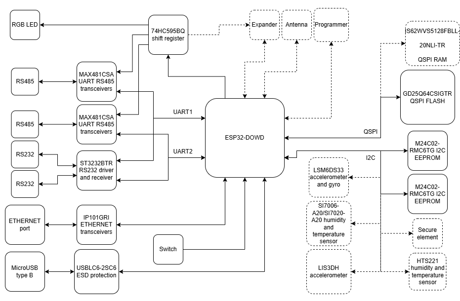
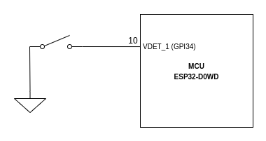
If the switch is soldered to the PCB, make sure there is also a resistor R52 located on the bottom layer of the board.
# RS232 and RS485
## {{@218#bkmrk-open-iot-and-iiot-ga}}
The gateway is equipped with 2 transceivers MAX481 that handle transmission in RS485 standard on each channel independently. Similar to RGB, each channel can be enabled by SIPO shift register 74HC595BQ.
To ensure transmission in RS232 standard there is also ST3232BTR IC which allows transmission on each channel independently.
It is possible to use only one pair of each interface at the same moment, because RS232 and RS485 use the same UART pins on the MCU.
# Ethernet PHY
## {{@218#bkmrk-open-iot-and-iiot-ga}}
| **Redisage PN**
| **P01**
| **P02**
|
| Ports
| RS232
| -
| -
|
| RS485
| -
| -
|
| RS232/RS485
| 2x
| 2x
|
| Microcontroller
| ESP32
|
| Wi-Fi**®**
| N/A
| 802.11 b/g/n 150 Mbps /
2.4 GHz
|
| SMA socket connector for 2.4G antenna
| 
| 
|
| Tactile switch
| 
| 
|
| Power
| Voltage
| 12-30 VDC
|
| Power
| < 1 W
|
| Frame ground protection
| yes
|
| Baud rate
| up to 115200 bps
|
| LED indicators
| power, link activity, programmable RGB
|
| RS485 termination
| 120 ohm manually enabled
|
| Connector
| RS232/RS485
| 8-pin terminal block max. 2.5 mm2 wire
|
| Power
| 3-pin terminal block max. 2.5 mm2 wire
|
| Ethernet
| RJ45
|
| Transmission
distance
| RS485
| max. 1,200 m at 9.6 kbps; max. 400 m at 115.2 kbps
(Belden 9841 2P twisted-pair cable, if different cables are used,
the transmission distance may change)
|
| RS232
| max. 15 m at 115.2 kbps
|
| Mounting and enclosure
| DIN rail, plastic PA - UL 94 V0, black/green
|
| Temperatures
| -40°C to +75°C operating and storage
|
| Humidity
| 10 - 90% RH, non-condensing
|
| ESD protection
| ±4 kV contact discharge / ±8 kV air discharge
|
| Certification
| CE, RoHS, EMC, LVD
|
| Norms
| 61000-6-2 - Immunity standard for industrial environments
61000-6-4 - Emission standard for industrial environments
|
### Pin assignments
| **P01**
[](https://doc.redisage.com/uploads/images/gallery/2024-06/p01-name-plate-label-v1-1099.png)
| **P02**
[](https://doc.redisage.com/uploads/images/gallery/2024-06/p02-name-plate-label-v1-1098.png)
|
# New Page
# New Page
# Introduction
## ESP32 Open IoT and IIoT Gateways (P01 & P02)
Open IoT Gateway is also called as a PAC (Programmable Automation Controller). PAC products combine the functionality and openness of a PC, the reliability of a programmable logic unit like PLC and the intelligence of I/O modules with flexible software tools for a wide range of applications from data acquisition, process control, motion control to energy and building management.
Our PAC family includes FreeRTOS PACs and MicroPython PACs for different requirements in OS, CPU and development platform.
The P01 and P02 Gateways are based on **ESP32 Xtensa LX6**.