| **Features** | [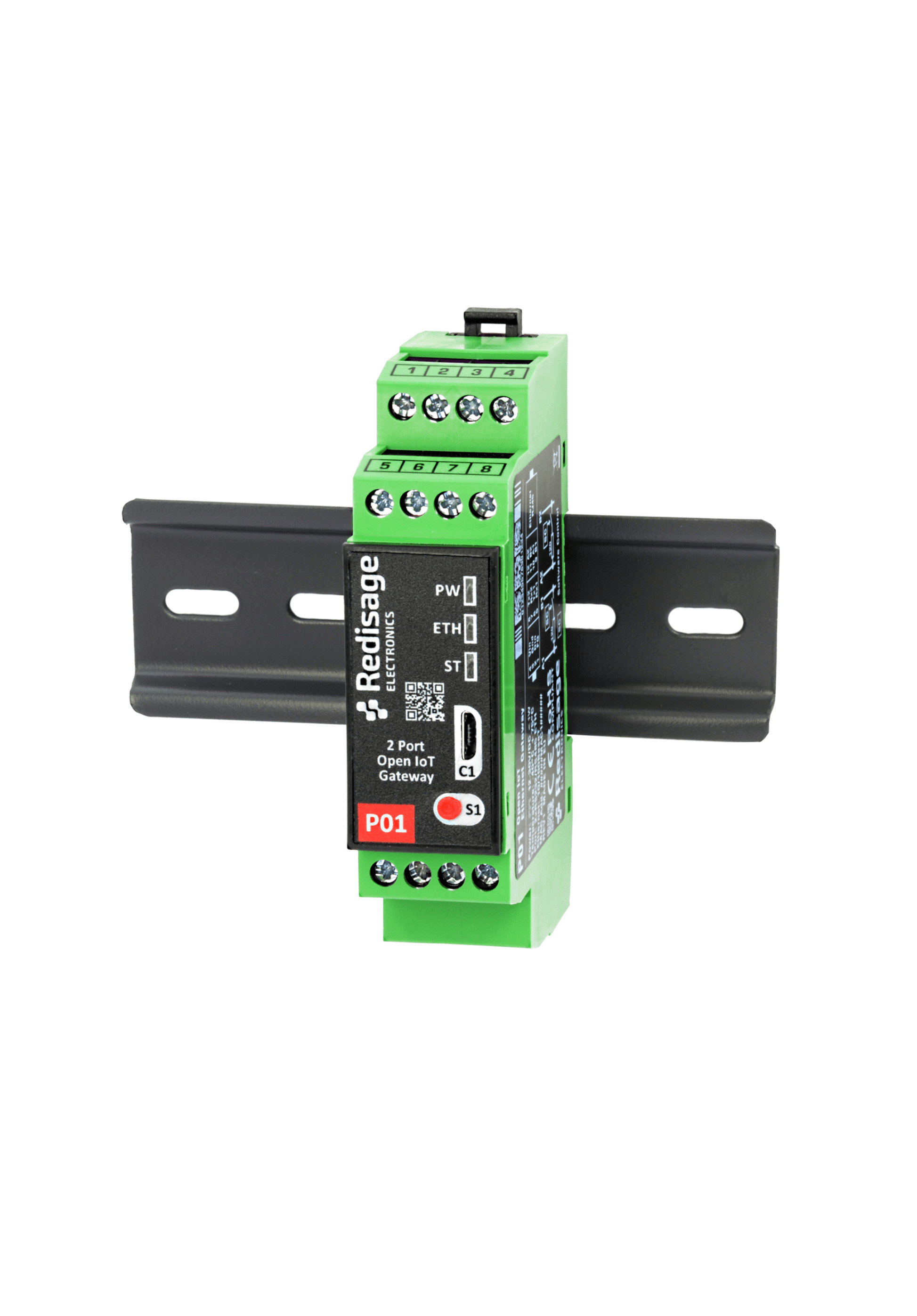](https://doc.redisage.com/uploads/images/gallery/2024-04/5e0098af-74b7-4f6a-84e2-63efb7875497-1.png) |
|---|---|
| Open IoT gateway | |
| ESD protection for the RS485 data line | |
| Power supply: +12 to +30 VDC | |
| Transmission speed up to 115200 bps | |
| Tx, Rx and power LED indicators | |
| RS485 embedded termination 120 ohm | |
| Optional W-iFi | |
| Operating temperatures: -40°C to +75°C | |
| DIN-rail mounting | |
| Dimensions: 90x56.4x22.5 mm | |
| **3 years warranty** | |
| **Customization of OEM is welcomed** |
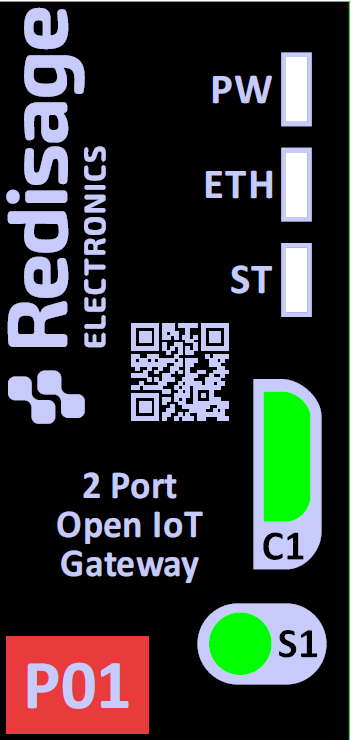
| **Gateway P01** | **Gateway P02** | ||||
| [](https://doc.redisage.com/uploads/images/gallery/2024-06/8kQimage.png) | [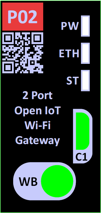](https://doc.redisage.com/uploads/images/gallery/2024-06/m6yimage.png) | ||||
| **LED indicator** | **Color** | **Function** | **LED indicator** | **Color** | **Function** |
| PW | Blue | Power | PW | Blue | Power |
| ETH | Green | Network activity | ETH | Green | Network activity |
| ST | Red / Green / Blue | Programmable LED | ST | Red / Green / Blue | Programmable LED |
In order to use the button instead of the antenna, the R52 resistor (near the microUSB connector, on the bottom side) has to be soldered to the board.
#### RS232 ports The device has 2 independent RS485 ports. [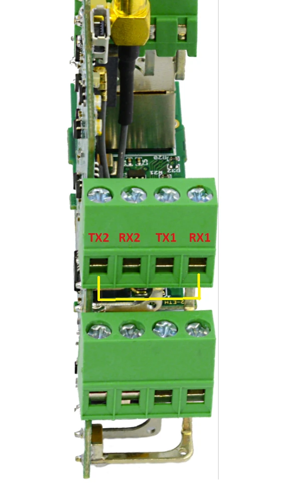](https://doc.redisage.com/uploads/images/gallery/2024-06/1qnimage.png) #### RS485 ports The device is equipped with two MAX481 transceivers that enable communication in the RS485 standard on two channels independently. [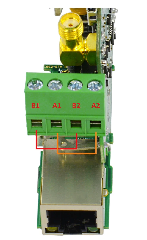](https://doc.redisage.com/uploads/images/gallery/2024-06/Ei3image.png)As the RS485\_1 / RS232\_1 and RS485\_2 / RS232\_2 standards use common microcontroller serial ports, it is possible to use only 1 interface from the pair at a time.
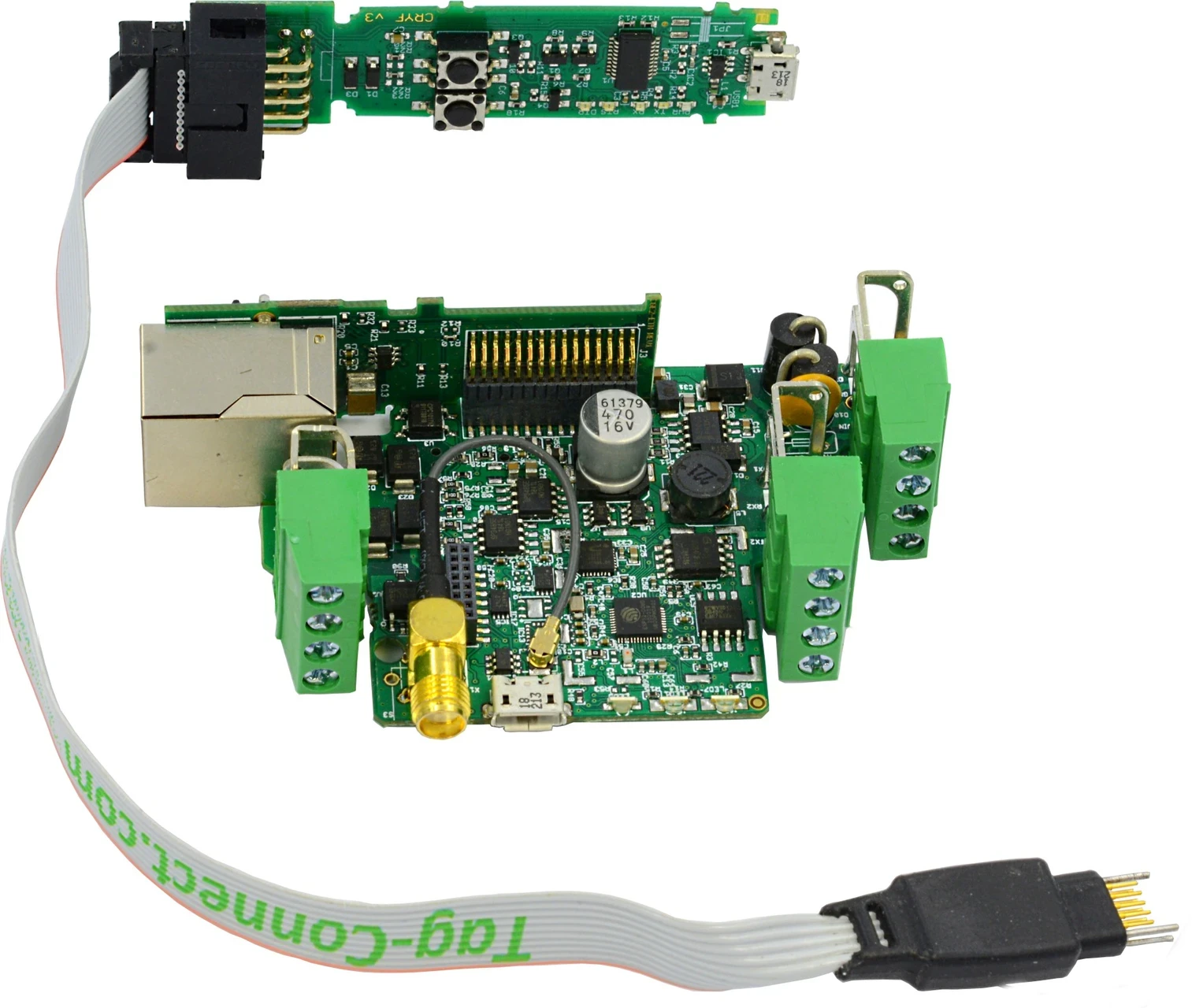
#### ETHERNET In order to support the Ethernet network interface communication, the network adapter available in the kit must be installed on the module (pay attention to its correct installation). This interface is supported by the external IP101G physical layer which communicates with the ESP32 microcontroller. [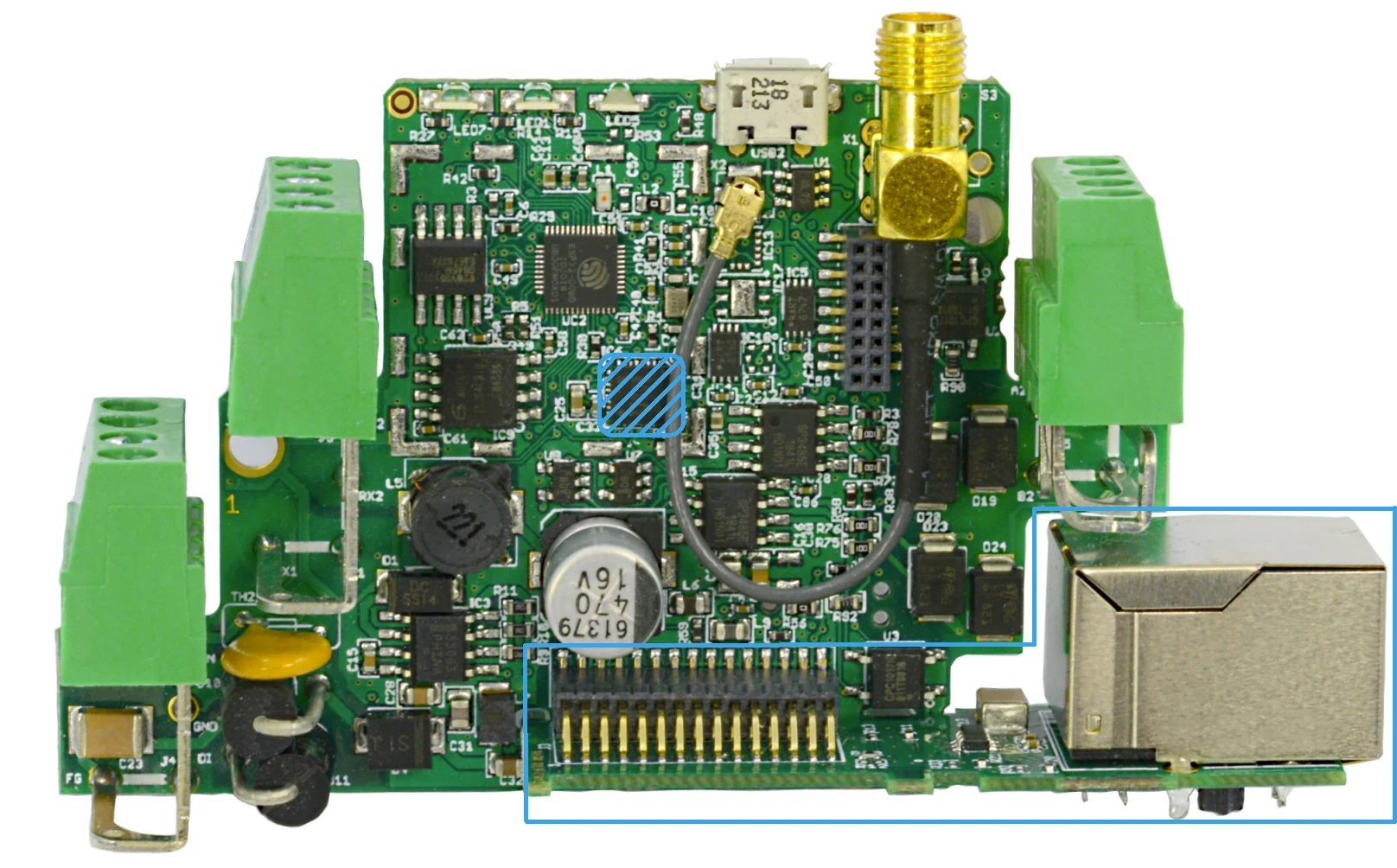](https://doc.redisage.com/uploads/images/gallery/2024-06/image-33.webp) #### #### Micro USB Connector You need the [C37](https://doc.redisage.com/books/usb-rs232-rs485-converters/page/usb-ftdi-converters-data-sheet) USB to UART FTDI Converter to connect the device with a PC console via USB. [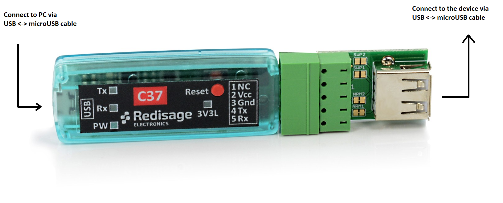](https://doc.redisage.com/uploads/images/gallery/2025-10/Yf5image.png) ### Programming The device can be programmed only with the external hardware programmer (for example [P03](https://doc.redisage.com/books/usb-rs232-rs485-converters/page/usb-ftdi-esp32-programmer-data-sheet)) connected via Tag-Connect connector ([P04](https://redisage.com/en/products/p04-tc2050-idc-nl-10-pin-no-legs-cable-with-ribbon-connector-124)). [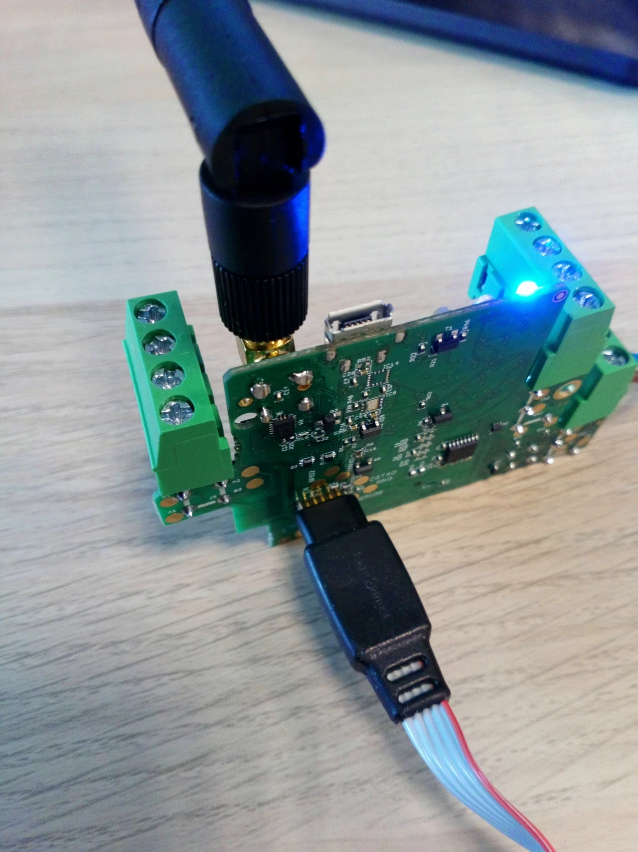](https://doc.redisage.com/uploads/images/gallery/2024-06/image-6.webp)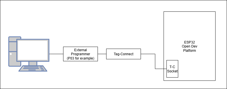
| [](https://doc.redisage.com/uploads/images/gallery/2024-06/image-4.webp) | [](https://doc.redisage.com/uploads/images/gallery/2024-06/image-6.webp) |
| [](https://doc.redisage.com/uploads/images/gallery/2024-04/67a06d6c-6dc6-4b4d-a4c4-25afbe706867.png) | [](https://doc.redisage.com/uploads/images/gallery/2024-04/5e24edfe-6c42-48ba-bfb8-7701b7b71c77.png) |
| **Element** | **Connection** |
| **LED** | |
| Power LED7 (blue) | +3V3 |
| ETHERNET LED1 (green) | ETH\_LED3/PHY\_AD3 |
| RGB programmable LED5 (red) | Q6 |
| RGB programmable LED5 (blue) | Q5 |
| RGB programmable LED5 (green) | Q4 |
| **74HC595BQ shift register** | |
| VCC | +3V3 |
| Q7S | Q7S |
| Q0 | Q0 |
| Q1 | Q1 |
| Q2 | Q2 |
| Q3 | RS485\_TER\_EN2 |
| Q4 | Q4 |
| Q5 | Q5 |
| Q6 | Q6 |
| Q7 | RS485\_TER\_EN1 |
| MR/ | CHIP\_PU (pull up) |
| OE/ | GND |
| DS | SERIAL\_REG\_DATA |
| SHCP | SHCP |
| STCP | STCP (pull down) |
| GND | GND |
| TPAD | GND |
| **MAX481CSA\_1 UART RS485 transceiver** | |
| DI | UART1\_TX |
| DE | UART1\_DIR |
| RE/ | UART1\_DIR |
| RO | UART1\_RX |
| A | A\_1 |
| B | B\_1 |
| **MAX481CSA\_2 UART RS485 transceivers** | |
| DI | UART2\_TX |
| DE | UART2\_DIR |
| RE/ | UART2\_DIR |
| RO | UART2\_RX |
| A | A\_2 |
| B | B\_2 |
| **ST3232BTR RS232 driver and receiver** | |
| C1+ | C1 (100 nF) |
| C1- | C1 (100 nF) |
| C2+ | C2 (100 nF) |
| C2- | C2 (100 nF) |
| T1IN | UART1\_TX |
| T2IN | UART2\_TX |
| R1OUT | UART1\_RX |
| R2OUT | UART2\_RX |
| V+ | C3 (100 nF) |
| V- | C4 (100 nF) |
| T1OUT | TXD1 |
| T2OUT | TXD2 |
| R1IN | RXD1 |
| R2IN | RXD2 |
| **USBLC6-2SC6 ESD protection** | |
| VCC | USB\_V |
| GND | GND |
| IO1\_A | DATA- |
| IO1\_B | CONSOLE\_RX |
| IO2\_A | DATA+ |
| IO2\_B | CONSOLE\_TX |
| **MicroUSB type B** | |
| V\_BUS | USB\_V |
| D- | DATA- (CONSOLE\_RX) |
| D+ | DATA+ (CONSOLE\_TX) |
| ID | GND |
| GND | GND |
| **M24C02-RMC6TG\_1 I2C EEPROM** | |
| E0 | GND |
| E1 | GND |
| E2 | +3V3 |
| VSS | GND |
| VCC | +3V3 |
| WC/ | GND |
| SCL | I2C\_SCL |
| SDA | I2C\_SDA |
| **M24C02-RMC6TG\_2 I2C EEPROM** | |
| E0 | +3V3 |
| E1 | +3V3 |
| E2 | GND |
| VSS | GND |
| VCC | +3V3 |
| WC/ | GND |
| SCL | I2C\_SCL (pull up) |
| SDA | I2C\_SDA (pull up) |
| **GD25Q64CSIGTR QSPI FLASH** | |
| CS# | SPICS0 |
| SO | SPIQ |
| WP# | SPIWP |
| VSS | GND |
| VCC | VDD\_SDIO |
| HOLD# | SPIHD |
| SCLK | SPICLK |
| SI | SPID |
| **IP101GRI ETHERNET transceivers** | |
| MDC | ETH\_MDC |
| MDIO | ETH\_MDIO |
| MDI\_TP | TXD+ |
| MDI\_TN | TXD- |
| MDI\_RP | RXD+ |
| MDI\_RN | RXD- |
| X2 | - |
| X1 | GND |
| RESET\_N | ETH\_RESET\_N (pull up) |
| ISET | ETH\_ISET (pull down) |
| LED0/PHY\_AD0 | ETH\_LED0/PHY\_AD0 (pull up) |
| LED3/PHY\_AD3 | ETH\_LED3/PHY\_AD3 (pull down) |
| TEST\_ON | - |
| REGOUT | C21 (100 nF), C35 (10 uF) |
| VDDIO | +3V3 |
| AVDD33 | +3V3 |
| GND | GND |
| TXEN | ETH\_TX\_EN |
| TXER/FXSD | - |
| TXCLK/50M\_CLKI | ETH\_CLK\_IN |
| TXD0 | ETH\_TXD0 |
| TXD1 | ETH\_TXD1 |
| TXD2 | - |
| TXD3 | - |
| RXDV/CRS\_DV/FX\_HEN | ETH\_RX\_CRS\_DV |
| RXCLK/50M\_CLKO | - |
| RXD0 | ETH\_RXD0 |
| RXD1 | ETH\_RXD1 |
| RXD2 | - |
| RXD3 | - |
| RXER/INTR\_32 | - |
| COL/RMII | ETH\_COL/RMII (pull up) |
| CRS/LEDMOD | - |
| **ESP32-DOWD** | |
| VDDA\_1 | +3V3 |
| LNA\_IN | ANT |
| VDD3P3\_1 | VDD3P3 (+3V3) |
| VDD3P3\_2 | VDD3P3 (+3V3) |
| SENSOR\_VP (GPI36) | USB\_DETECT (pull down) |
| SENSOR\_CAPP (GPI37) | UART2\_RX |
| SENSOR\_CAPN (GPI38) | GPI\_38 |
| SENSOR\_VN (GPI39) | P\_DETECT (pull up) |
| CHIP\_PU | CHIP\_PU (pull up) |
| VDET\_1 (GPI34) | BUTTON\_IN (pull up) |
| VDET\_2 (GPI35) | UART1\_RX |
| 32K\_XP (GPIO32) | UART1\_TX |
| 32K\_XN (GPIO33) | SHCP |
| GPIO25 | ETH\_RXD0 |
| GPIO26 | ETH\_RXD1 |
| GPIO27 | ETH\_RX\_CRS\_DV |
| MTMS (GPIO14) | UART1\_DIR |
| MTDI (GPIO12) | UART2\_DIR |
| VDD3P3\_RTC | +3V3 |
| MTCK (GPIO13) | I2C\_SDA (pull up) |
| MTDO (GPIO15) | STCP (pull down) |
| GPIO2 | I2C\_SCL (pull up) |
| GPIO0 | ETH\_CLK\_IN, SPICS1 |
| GPIO4 | SERIAL\_REG\_DATA |
| GPIO16 | ETH\_CLK |
| VDD\_SDIO | VDD\_SDIO |
| GPIO17 | SPICS1 |
| SD\_DATA\_2 (GPIO9) | SPIHD |
| SD\_DATA\_3 (GPIO10) | SPIWP |
| SD\_CMD (GPIO11) | SPICS0 |
| SD\_CLK (GPIO6) | SPICLK |
| SD\_DATA\_0 (GPIO7) | SPIQ |
| SD\_DATA\_1 (GPIO8) | SPID |
| GPIO5 | UART2\_TX |
| GPIO18 | ETH\_MDIO |
| GPIO23 | ETH\_MDC |
| VDD3P3\_CPU | +3V3 |
| GPIO19 | ETH\_TXD0 |
| GPIO22 | ETH\_TXD1 |
| U0RXD (GPIO3) | CONSOLE\_RX |
| U0TXD (GPIO1) | CONSOLE\_TX |
| GPIO21 | ETH\_TX\_EN |
| VDDA\_2 | +3V3 |
| XTAL\_N | XTAL\_N |
| XTAL\_P | XTAL\_P |
| VDDA\_3 | +3V3 |
| CAP2 | CAP2 |
| CAP1 | CAP1 |
| GND | GND |
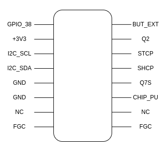
| **Element** | **Connection** |
| **Expander** | |
| 1 | FGC |
| 2 | - |
| 3 | CHIP\_PU (pull up) |
| 4 | Q7S |
| 5 | SHCP |
| 6 | STCP (pull down) |
| 7 | Q2 |
| 8 | BUT\_EXT |
| 9 | GPI\_38 |
| 10 | +3V3 |
| 11 | I2C\_SCL (pull up) |
| 12 | I2C\_SDA (pull up) |
| 13 | GND |
| 14 | GND |
| 15 | - |
| 16 | FGC |
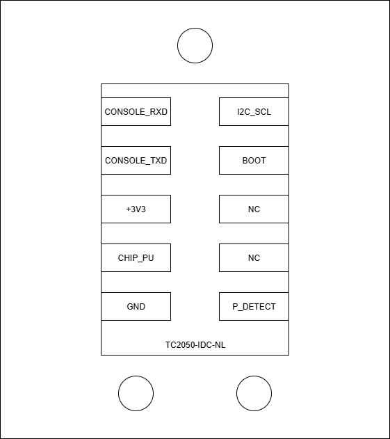
| **Programmer** | |
| 1 | CONSOLE\_RX |
| 2 | CONSOLE\_TX |
| 3 | +3V3 |
| 4 | CHIP\_PU |
| 5 | GND |
| 6 | P\_DETECT |
| 7 | - |
| 8 | - |
| 9 | BOOT |
| 10 | I2C\_SCL |
| **870-62WS5128 QSPI RAM** | |
| CS# | SPICS1 |
| SO | SPIQ |
| WP# | SPIWP |
| VSS | GND |
| VCC | VDD\_SDIO |
| HOLD# | SPIHD |
| SCLK | SPICLK |
| SI | SPID |
| **Secure element** | |
| SCL | I2C\_SCL (pull up) |
| SDA | I2C\_SDA (pull up) |
| VCC | +3V3 |
| IO | - |
| GND | GND |
| **SI7006-A20/SI7020-A20 humidity and temperature sensor** | |
| SDA | I2C\_SDA (pull up) |
| GND | GND |
| DNC1 | - |
| SCL | I2C\_SCL (pull up) |
| VDD | +3V3 |
| DNC2 | - |
| **HTS221 humidity and temperature sensor** | |
| VDD | +3V3 |
| CS | +3V3 |
| GND | GND |
| SCL/SPC | I2C\_SCL (pull up) |
| SDA/SDI/SDO | I2C\_SDA (pull up) |
| DRDY | - |
| **LSM6DS33 accelerometer and gyro** | |
| GND | GND |
| GND | GND |
| RES | GND |
| RES | GND |
| RES | GND |
| RES | GND |
| INT1 | - |
| INT2 | - |
| CS | +3V3 |
| SDO | - |
| SDA | I2C\_SDA (pull up) |
| SCL | I2C\_SCL (pull up) |
| VDDIO | +3V3 |
| VDD | +3V3 |
| RES | GND |
| NC | - |
| **LIS3DH accelerometer** | |
| VDD\_IO | +3V3 |
| NC | - |
| NC | - |
| SCL/SPC | I2C\_SCL (pull up) |
| GND | GND |
| SDA/SDI/SDO | I2C\_SDA (pull up) |
| SDO/SAO | - |
| CS | +3V3 |
| INT2 | - |
| RES | GND |
| INT1 | - |
| GND | GND |
| ADC3 | - |
| VDD | +3V3 |
| ADC2 | - |
| ADC1 | - |
| **IP101GRI ETHERNET transceivers** | |
| ETH\_RESET\_N | Q1 |