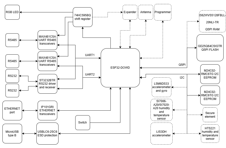
# Peripherals
# Simplified Block Diagram
## {{@218#bkmrk-open-iot-and-iiot-ga}}
Optional elements are marked with the dashed lines.
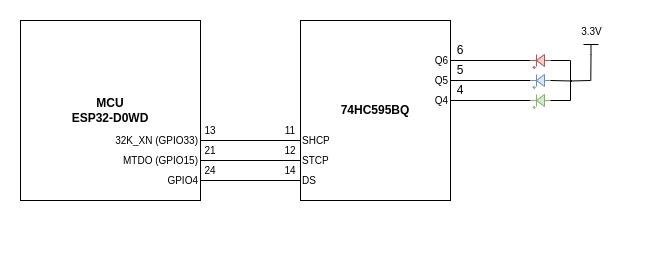
# RGB LED
## {{@218#bkmrk-open-iot-and-iiot-ga}}
RGB LED is controlled by SIPO shift register 74HC595BQ.
- SHCP - shift register clock input
- STCP - storage register clock input
- DS - serial data input
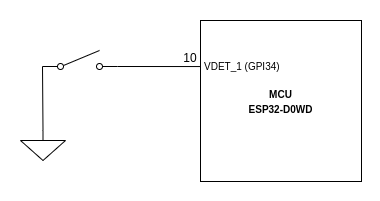
# Switch
## {{@218#bkmrk-open-iot-and-iiot-ga}}
The Open IoT Gateway P01 variant contains a tactile switch. The PCB has hardware pull-up designed into it so debouncing effect is eliminated.
If the switch is soldered to the PCB, make sure there is also a resistor R52 located on the bottom layer of the board.
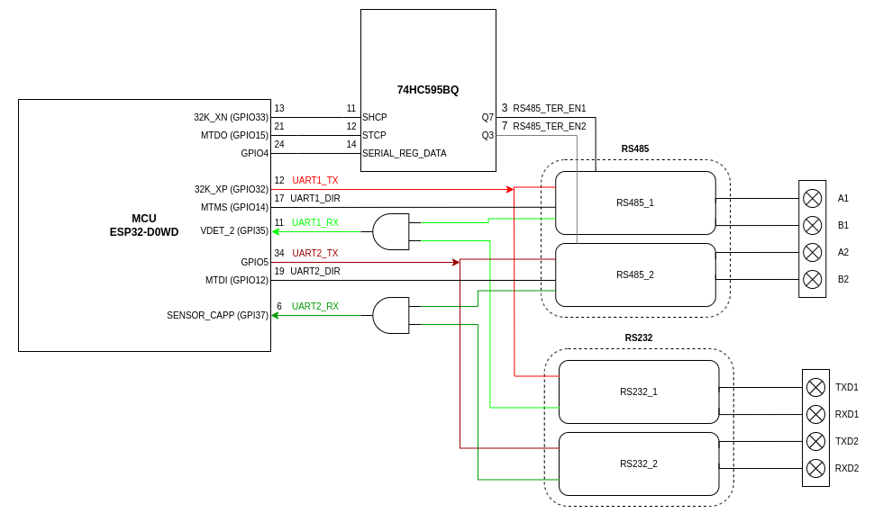
# RS232 and RS485
## {{@218#bkmrk-open-iot-and-iiot-ga}}
The gateway is equipped with 2 transceivers MAX481 that handle transmission in RS485 standard on each channel independently. Similar to RGB, each channel can be enabled by SIPO shift register 74HC595BQ.
To ensure transmission in RS232 standard there is also ST3232BTR IC which allows transmission on each channel independently.
It is possible to use only one pair of each interface at the same moment, because RS232 and RS485 use the same UART pins on the MCU.
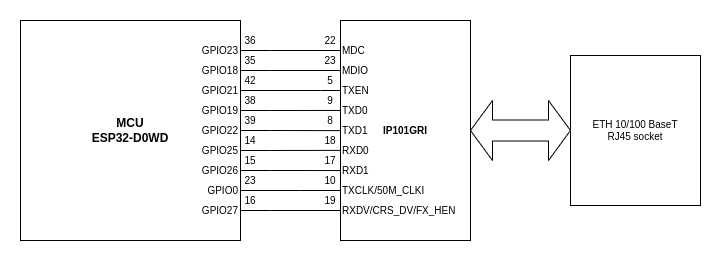
# Ethernet PHY
## {{@218#bkmrk-open-iot-and-iiot-ga}}
The Ethernet interface is provided by the IP101G physical layer. There is also an external board with RJ45 socket which ensures wired connection to the network.
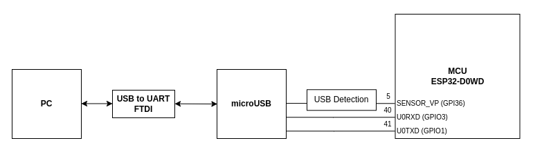
# MicroUSB
## {{@218#bkmrk-open-iot-and-iiot-ga}}
MicroUSB ensures access straight to UART interface (UART0). The Open IoT Gateway does not have inbuild FTDI converter so an external USB to UART FTDI converter is needed to run a serial port monitor on a PC.
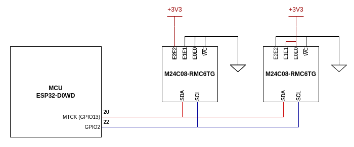
# I2C EEPROM
## {{@218#bkmrk-open-iot-and-iiot-ga}}
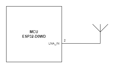
# Antenna
## {{@218#bkmrk-open-iot-and-iiot-ga}}
The Open IoT and IIoT Gateway P02 variant contains SMA connector for a 2.4G antenna.
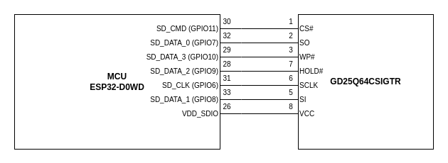
# QSPI Flash
## {{@218#bkmrk-open-iot-and-iiot-ga}}
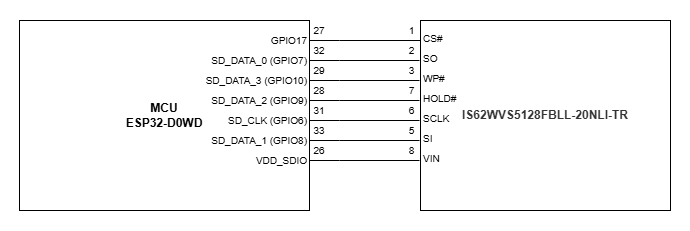
# QSPI RAM
## {{@218#bkmrk-open-iot-and-iiot-ga}}
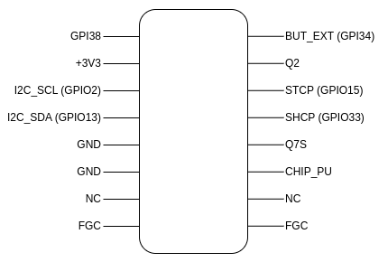
# Expander
## {{@218#bkmrk-open-iot-and-iiot-ga}}
The female goldpin connector allows easy access to different signals. It might be useful during analysis of the board.
- GPI38 - general purpose input pin, connected directly to the MCU (might work only as an input pin)
- 3V3 - 3.3 V voltage
- I2C\_SCL and I2C\_SDA - main lines of the I2C interface
- GND - ground
- NC - not connected
- FGC - frame ground connection
- BUT\_EXT - switch test line ('1' is set by default)
- Q2 - Q2 pin of the shift register
- STCP - storage register clock input
- SHCP - shift register clock input
- Q7S - serial data output pin of shift register
- CHIP\_PU - chip power up signal ('1' - enables the chip)
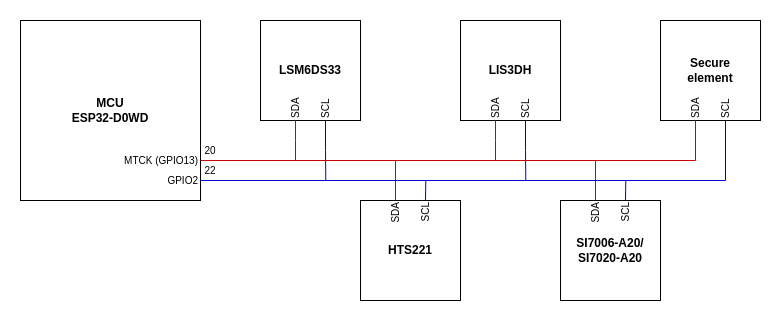
# I2C Sensors
## {{@218#bkmrk-open-iot-and-iiot-ga}}
- LSM6DS33 - 3D accelerometer and 3D gyroscope
- LIS3DH - 3-axis "nano" accelerometer
- HTS221 - capacitive digital sensor for relative humidity and temperature measurements
- SI7006-A20 / SI7020-A20 - humidity and temperature sensor
- Secure element